STMM-120-02-G-D Samtec Inc, STMM-120-02-G-D Datasheet
STMM-120-02-G-D
Manufacturer Part Number
STMM-120-02-G-D
Description
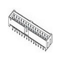
2MM TERMINAL STRIPS
Manufacturer
Samtec Inc
Type
Shrouded Headerr
Datasheet
1.STMM-120-02-G-D.pdf
(1 pages)
Specifications of STMM-120-02-G-D
Pitch (mm)
2mm
Gender
HDR
Number Of Contacts
40POS
Number Of Contact Rows
2
Mounting Style
Through Hole
Body Orientation
Straight
Contact Plating
Gold Over Nickel
Operating Temp Range
-55C to 125C
Termination Method
Solder
Current Rating (max)
3A
Contact Material
Phosphor Bronze
Housing Material
Nylon
Product Height (mm)
4.8mm
Product Length (mm)
46.17mm
Product Depth (mm)
6.51mm
Lead Free Status / RoHS Status
Compliant
Mates with:
SQT, SQW, ESQT,
SMM, TCSD
For complete specifi cations and
recommended PCB layouts
see www.samtec.com?STMM,
www.samtec.com?LTMM,
www.samtec.com?ZSTMM or
www.samtec.com?ZLTMM
Insulator Material:
High Temperature
Nylon
Terminal Material:
Phosphor Bronze
Plating:
Sn or Au over 50µ"
(1,27µm) Ni
Current Rating:
3A @ 80°C ambient
Operating Temp Range:
-55°C to +105°C with Tin;
-55°C to +125°C with Gold
RoHS Compliant:
Yes
Processing:
Lead–Free Solderable:
Yes
SMT Lead Coplanarity:
(0,10mm) .004" max
Note: This Series is
non-standard, non-returnable.
SHROUDED IDC HEADER & STACKER
Note: Other Gold plating
options available.
Contact Samtec.
CSF-210
SPECIFICATIONS
(2,00mm) .0787"
STMM, LTMM, ZSTMM, ZLTMM SERIES
= Elevated Connector Strip
(2,97)
(0,51)
STRIP
.117
TYPE
.020
(2,00)
.0787
05, 08, 10, 12, 13, 15, 17, 20, 22, 25
= Connector Strip
ZSTMM
ZSTMM
ZLTMM
ZLTMM
LTMM/
STMM/
STRIP
= Cable Strip
STMM
TYPE
LTMM
Cable Strip
= Elevated
STMM
LTMM
02 04
01 03
No. of Positions
No. of Positions
(2,00) .0787 x
(2,00) .0787 x
+ (0,61) .024
+ (4,39) .173
ZSTMM / ZLTMM
(2,00) .0787
1
Y
(3,55)
.140
X
X
(Call Samtec for other sizes)
PER ROW
NO. PINS
No. of Positions
No. of Positions
(2,00) .0787 x
(2,00) .0787 x
+ (2,39) .094
+ (6,17) .243
LTMM–108–02–G–D–RA
WWW.SAMTEC.COM
Y
.020 SQ
(0,51)
STYLE
(0,38)
LEAD
.015
(2,29)
.090
(6,00)
MIN
-75
-62
-65
-73
-63
-66
-69
-74
-70
-71
-72
Specify ZSTMM & ZLTMM
.237
(4,80)
.190
= STMM & LTMM
(10,08) 0.397
(10,49) 0.413
(12,09) 0.476
(14,10) 0.555
(15,09) 0.594
(15,60) 0.614
(17,09) 0.673
(17,60) 0.693
(21,08) 0.830
(21,62) 0.851
(9,58) 0.377
from chart
(OAL)
STYLE
LEAD
–02
B
(3,05)
.120
(0,89)
.035
(2,29)
(OAL)
.090
B
(1,52)
MAX BODY
(11,94) 0.470
(12,93) 0.509
(13,44) 0.529
(14,94) 0.588
(15,44) 0.608
(18,92) 0.745
(19,46) 0.766
.060
(7,42) 0.292
(7,92) 0.312
(8,33) 0.328
(9,93) 0.391
(3,18) .125
HEIGHT
HEIGHT
BODY
(6,35)
.250
MIN
(7,79)
.307
–RA
ZSTMM–112–75–L–D–285
PLAT ING
OPTION
(0,38)
.015
(2,00)
(1,27)
.0787
.050
D
(STMM & LTMM only)
(STMM & LTMM only)
= ZSTMM & ZLTMM
= Surface Mount
Leave blank for
–“XXX”
= Right Angle
Through-hole
Body Height
Gold on post, Gold fl ash on tail
–SM
–RA
= 10µ" (0,25µm) Gold on post,
HEIGHT
BODY
Matte Tin on tail
= 20µ" (0,51µm)
= Matte Tin
–G
–L
–T
STMM–113–02–G–D
= Tape & Reel
OPTION
–“XX”
Film Pick &
= Polarized
= (7,50mm)
OTHER
(–SM only)
(-SM only)
placement
(-SM only)
= Locking
Place Pad
.295" DIA
required)
Position
–LC
(Manual
–TR
–K
Clip
Related parts for STMM-120-02-G-D
Image
Part Number
Description
Manufacturer
Datasheet
Request
R

Part Number:
Description:
Conn Shrouded Header HDR 40 POS 2mm Solder ST SMD T/R
Manufacturer:
Samtec Inc
Datasheet:
Part Number:
Description:
Conn Shrouded Header HDR 40 POS 2mm Solder ST Thru-Hole Tube
Manufacturer:
Samtec Inc
Datasheet:
Part Number:
Description:
2011 SAMTEC FULL LINE CATALOGUE
Manufacturer:
Samtec Inc
Part Number:
Description:
SAMTEC CATALOGUE JUNE2012
Manufacturer:
Samtec Inc
Part Number:
Description:
Customer specified Board Stacker, 2x03, pitch 2.00mm, SMD, T&R
Manufacturer:
Samtec Inc
Part Number:
Description:
polarized micro socket, 19pos., pitch 1mm, alignment pin, p&p pad, SMD
Manufacturer:
Samtec Inc
Part Number:
Description:
Basic Socket Strip, 2x20 pos., pitch0.80mm, SMD
Manufacturer:
Samtec Inc
Part Number:
Description:
low profile dual wipe socket, 2x12pos., pitch 1,27mm, bottom entry, SMD
Manufacturer:
Samtec Inc