CRA12E08034701FRB8 Vishay, CRA12E08034701FRB8 Datasheet - Page 2
CRA12E08034701FRB8
Manufacturer Part Number
CRA12E08034701FRB8
Description
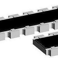
Resistor Networks & Arrays 8Term 4.7Kohms 1% Convex
Manufacturer
Vishay
Type
Arrayr
Series
CRA12E, CRA12Sr
Specifications of CRA12E08034701FRB8
Technology
Thick Film
Resistance
4.7kohm
Power Rating
1/8W
Power Rating Per Resistor
125mW
Number Of Resistors
4
Tolerance (+ Or -)
1%
Circuit Designator
ISOL
Mounting Style
Surface Mount
Temperature Coefficient
±100
Military Standard
Not Required
Operating Temp Range
-55C to 150C
No. Of Terminals
8
Case Style
Molded
Failure Rate
Not Required
Termination Style
Convex
Terminal Pitch
1.27
Product Length (mm)
5.08mm
Product Depth (mm)
3.05mm
Product Height (mm)
0.53mm
Product Type
Arrays
Circuit Type
Isolated
Tolerance
1 %
Number Of Pins
8
Operating Temperature Range
- 55 C to + 150 C
Dimensions
3.05 mm W x 5.08 mm L x 0.53 mm H
Lead Spacing
0.79 mm
Voltage Rating
50 Volts
Lead Free Status / RoHS Status
Not Compliant


Document Number 31003
Revision 03-Sep-03
CIRCUIT SCHEMATICS
Pin 1
4
PERFORMANCE
MODEL
CRA
12E
12E
12S
12E
12S
12E
TEST
Endurance Test at 70 C
per EIA 575-3.14
Overload
per EIA 575-3.6
Thermal Shock
Moisture Resistance
Resistance to Soldering Heat
EIA 575-3.8
High Temperature Exposure
Low Temperature Operations
Solderability & Leaching
4 pin 8 pin 10 pin
4 pin8 pin10
01 Circuit
NO#
PIN
03 Circuit
Tol - 0.15 - 0.15 - 0.15 - 0.25 - 0.2 - 0.1 - 0.1 - 0.15
10
10
16 10.30 0.79
4
8
8
8-Terminal device
e
PIN 1
pin
2.54 0.79
5.08 0.79
5.08 0.79 0.89 0.51 0.38 1.27 0.53 3.05
6.40 0.79
6.40 0.79 0.89 0.51 0.38 1.27 0.53 3.05
L
16 pin
A
a
16 pin
A
DIMENSIONS [in millimetres]
a
103
A*
-
-
-
-
Pin 1
e
pin # 1
0.51 0.38 1.27 0.53 3.05
0.51 0.38 1.27 0.53 3.05
0.51 0.38 1.27 0.53 3.05
0.51 0.38 1.27 0.53 3.05
d
B
4 pin
For Technical Questions, contact: ff2aresistors@vishay.com
CONDITIONS OF TEST
1000 hours at 70˚C, 1.5 hours "ON", 0.5 hours "OFF"
Short time overload 2.5 x rated continuous working voltage
for 5 seconds. Not to exceed 2 x max operating voltage
per EIA 575-3.5
per EIA 575-3.10
10 seconds at 260 C solder bath temperature
per EIA 575-3.7
per EIA 575-3.6
EIA 575-3.12
B*
S - Version
8 pin
02 Circuit
20 Circuit
Thick Film, Resistor Array
P
*
T
10 pin
W
Derating
The dimensions shown are for 8 pin part. For parts with different
pin numbers use the same pitch and add or substract pads as
required.
WAVE
REFLOW
120
100
80
60
40
20
0
- 55
-25
2.2
2.2
c
SOLDER PAD DIMENSIONS [in millimetres]
0
4.3
3.9
w
25
E - Version
103
0.57
0.57
d
50
CRA12E and S
1.27
1.27
p
70
TEST RESULTS
Ambient Temperature in C
75
95% Coverage
0.71
0.71
Vishay Dale
100
a
1.0%
0.5%
0.5%
1.0%
2.0%
1.0%
0.5%
www.vishay.com
125
1.05
0.86
b
150 175
1.09
1.09
e
11
Related parts for CRA12E08034701FRB8
Image
Part Number
Description
Manufacturer
Datasheet
Request
R

Part Number:
Description:
THICK FILM RESISTORS ARRAY, CRA12E0803 1K 1% RB8
Manufacturer:
Vishay
Part Number:
Description:
Resistor Network,Thick Film,1.5KOhms,50WV,5+/-% Tol,-200,200ppm-TC,2012-Case
Manufacturer:
Vishay
Part Number:
Description:
Resistor Network,Thick Film,150Ohms,50WV,5+/-% Tol,-200,200ppm-TC,2012-Case
Manufacturer:
Vishay
Part Number:
Description:
Resistor Network,Thick Film,2.2KOhms,50WV,5+/-% Tol,-200,200ppm-TC,2012-Case
Manufacturer:
Vishay
Part Number:
Description:
Resistor Network,Thick Film,22Ohms,50WV,5+/-% Tol,-200,200ppm-TC,2012-Case
Manufacturer:
Vishay
Part Number:
Description:
Resistor Network,Thick Film,330Ohms,50WV,5+/-% Tol,-200,200ppm-TC,2012-Case
Manufacturer:
Vishay
Part Number:
Description:
Resistor Network,Thick Film,68Ohms,50WV,5+/-% Tol,-200,200ppm-TC,2012-Case
Manufacturer:
Vishay
Part Number:
Description:
Resistor Network,Thick Film,82Ohms,50WV,5+/-% Tol,-200,200ppm-TC,2012-Case
Manufacturer:
Vishay
Part Number:
Description:
RESISTOR, RES ARRAY, 1KOHM, 125mW, ±5%
Manufacturer:
Vishay
Part Number:
Description:
357-036-542-201 CARDEDGE 36POS DL .156 BLK LOPRO
Manufacturer:
Vishay
Datasheet:
Part Number:
Description:
357-036-542-201 CARDEDGE 36POS DL .156 BLK LOPRO
Manufacturer:
Vishay
Datasheet:
Part Number:
Description:
357-036-542-201 CARDEDGE 36POS DL .156 BLK LOPRO
Manufacturer:
Vishay
Datasheet:
Part Number:
Description:
357-036-542-201 CARDEDGE 36POS DL .156 BLK LOPRO
Manufacturer:
Vishay
Datasheet:
Part Number:
Description:
357-036-542-201 CARDEDGE 36POS DL .156 BLK LOPRO
Manufacturer:
Vishay
Datasheet: