861SSR410-DC-1 Magnecraft / Schneider Electric, 861SSR410-DC-1 Datasheet - Page 26
861SSR410-DC-1
Manufacturer Part Number
861SSR410-DC-1
Description
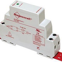
Solid State Relays SSR, Zero cross, SCR SPST-NO,10A,480Vac
Manufacturer
Magnecraft / Schneider Electric
Specifications of 861SSR410-DC-1
Control Voltage Range
3 VDC to 32 VDC
Load Voltage Rating
48 VAC to 480 VAC
Load Current Rating
10 A
Contact Form
SPST - NO
Mounting Style
DIN Rail
Control Voltage Type
DC
Operating Voltage Range
48VAC To 480VAC
Peak Surge Current
500A
Contact Configuration
SPST-NO
Load Current
10A
Lead Free Status / RoHS Status
Lead free / RoHS Compliant
Lead Free Status / RoHS Status
Lead free / RoHS Compliant, Lead free / RoHS Compliant


Application Data
26
(continued)
Magnecraft
Thermal Considerations
One of the major considerations when using a SSR is properly managing the heat
that is generated when switching currents are higher than 5 A� In this scenario
mount the base plate of the SSR on a good heat conductor, such as aluminum, and
use a good thermal transfer medium, such as thermal grease or a heat transfer pad�
Using this technique, the SSR case to heat sink thermal resistance is reduced to a
negligible value of 0.1 ˚C/W.
Thermal Calculations
To understand the thermal relationship between the output semiconductor junction (T
and the surrounding ambient temperature (T
drop of temperature, from junction to ambient (T
thermal resistances multiplied by the junction power dissipation�
To use the equation, the maximum junction temperature of the semiconductor must
be known, typically 125 ˚C, along with the actual power dissipation. When these two
parameters are known, the third can be found as shown in the following example:
1) Determine the maximum allowable ambient temperature, for a 1 ˚C/W heat sink
and a 10 A load (12 watts) with a maximum allowable junction temperature (T
of 100 ˚C, and assume a thermal resistance from junction to case (R
2) Determine the required heat sink thermal resistance, for 71.2 ˚C maximum
ambient temperature and a 10 amp load (12 watts):
3) Determine maximum load current, for 1 ˚C/W heat sink and 71.2 ˚C ambient temperature:
Where: T
T
R
P
J
өSA
- T
A
= P (R
= 12 (1.3 + 0.1 + 1.0) hence:
= 28.8
= T
= 100 - 71.2 - (1.3 + 0.1)
= 1 °C/W
=
=
= 12 watts
T
P
R
R
R
A
J
(R
өJC
өCS
өSA
J
1.3 + 0.1 + 1.0
өJC
P
T
- T
= Junction Temperature, °C
= Ambient Temperature, °C
= Power Dissipation (I
= Thermal Resistance, junction to case, °C/W
= Thermal Resistance, case to sink, °C/W
= Thermal Resistance, sink to ambient, °C/W
12
100 - 71.2
J
өJC
- T
+ R
®
A
T
J
- (R
A
+ R
Solid State Relays
- T
өCS
= P (R
өJC
A
өCS
+ R
+ R
+ R
өSA
өJC
өCS
өSA
)
A
+ R
) measure the temperature gradient, or
)
)
hence:
J
- T
өCS
A
); which equals the sum of the
+ R
LOAD
өSA
I
T
3 E
LOAD
A
)
= T
= 100–28.8
= 71.2 °C
DROP
=
= 10 amperes
J
E
1.2
) watts
–28.8
12
өJC
DROP
P
) of 1�3:
J
)
J
)
Related parts for 861SSR410-DC-1
Image
Part Number
Description
Manufacturer
Datasheet
Request
R

Part Number:
Description:
Solid State Relays SSR, Zero cross, SCR SPST-NO,10A,480Vac
Manufacturer:
Magnecraft / Schneider Electric
Datasheet:

Part Number:
Description:
861 SOLID STATE RELAYS
Manufacturer:
Magnecraft / Schneider Electric
Datasheet:
Part Number:
Description:
861 SOLID STATE RELAYS
Manufacturer:
Magnecraft / Schneider Electric
Datasheet:

Part Number:
Description:
Solid State Relays 3A/50VAC SPST-NO
Manufacturer:
Magnecraft / Schneider Electric
Datasheet:

Part Number:
Description:
HEAT SINK MAGNECRAFT
Manufacturer:
Magnecraft / Schneider Electric
Datasheet:

Part Number:
Description:
Bracket, Panel Mounting; Use with 711, 712, TDRSRX/SOX Series Magnecraft Relays
Manufacturer:
Magnecraft/Schneider Electric
Datasheet:
Part Number:
Description:
Bracket, DIN Rail Mounting; Use with 711, 712, TDRSRX/SOX Series Magnecraft Relays
Manufacturer:
Magnecraft/Schneider Electric
Datasheet:
Part Number:
Description:
Solid State Relays SPST-NO 48 to 480 VAC
Manufacturer:
Magnecraft / Schneider Electric
Datasheet:
Part Number:
Description:
Solid State Relays SPST-NO 48 to 480 VAC
Manufacturer:
Magnecraft / Schneider Electric
Datasheet:
Part Number:
Description:
Solid State Relays SPST-NO 3 to 50 VDC
Manufacturer:
Magnecraft / Schneider Electric
Datasheet:
Part Number:
Description:
Solid State Relays SPST-NO 48 to 600 VAC
Manufacturer:
Magnecraft / Schneider Electric
Datasheet:
Part Number:
Description:
Solid State Relays SPST-NO 3 to 150 VDC
Manufacturer:
Magnecraft / Schneider Electric
Datasheet:
Part Number:
Description:
Solid State Relays SPST-NO 48 to 600 VAC
Manufacturer:
Magnecraft / Schneider Electric
Datasheet:
Part Number:
Description:
Solid State Relays SPST-NO 24 to 280 VAC
Manufacturer:
Magnecraft / Schneider Electric
Datasheet:
Part Number:
Description:
Relay; E-Mech; Power; On Delay; SPDT; Cur-Rtg 15A; Ctrl-V 120AC; Vol-Rtg 240/24AC/DC
Manufacturer:
Magnecraft/Schneider Electric
Datasheet: