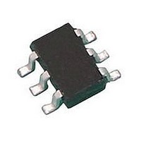
LH1525AAB Vishay, LH1525AAB Datasheet - Page 7

LH1525AAB
Manufacturer Part Number
LH1525AAB
Description
Solid State Relays Normally Open Form 1A 400V
Manufacturer
Vishay
Datasheet
1.LH1525AABTR.pdf
(9 pages)
Specifications of LH1525AAB
Load Voltage Rating
400 V
Load Current Rating
0.25 A
Contact Form
1 Form A
Output Device
MOSFET
Maximum Operating Temperature
+ 85 C
Minimum Operating Temperature
- 40 C
Package / Case
PDIP-6
Output Type
AC, DC
Load Voltage Max
400V
Load Current
125mA
On State Resistance Max
36ohm
Contact Configuration
SPST-NO
Isolation Voltage
5300V
Forward Current If
330µA
Relay Terminals
SMD
Load Current Rms Max
125mA
Mounting Style
SMD/SMT
Case Color
Black
Relay Type
Solid State
Lead Free Status / RoHS Status
Lead free / RoHS Compliant
Lead Free Status / RoHS Status
Lead free / RoHS Compliant, Lead free / RoHS Compliant
Available stocks
Company
Part Number
Manufacturer
Quantity
Price
Company:
Part Number:
LH1525AAB
Manufacturer:
AD
Quantity:
5 510
Company:
Part Number:
LH1525AABTR
Manufacturer:
Vishay Semiconductors
Quantity:
1 880
Part Number:
LH1525AABTR
Manufacturer:
VISHAY/威世
Quantity:
20 000
APPLICATIONS
INPUT CONTROL
The LH1525 low turn-on current SSR has highly sensitive
photodetection circuits that will detect even the most minute
currents flowing through the LED. Leakage current must be
considered when designing a circuit to turn on and off these
relays.
Figure 23 shows a typical logic circuit for providing LED
drive current. R
of current flowing through the LED. For 5 V operation, a
2700 resistor will limit the drive current to about 1.4 mA.
Where high-speed actuation is desirable, use a lower value
resistor for R
required with the LH1525 relay.
R
high output (V
resistance is set at a high value to minimize the overall
current drawn from the VS. The primary purpose of this
resistor is to keep the differential voltage across the LED
below its turn-on threshold. LED dropout voltage is graphed
vs. temperature in the typical performance characteristics
section. When the logic gate is high, leakage current will flow
through R
PACKAGE DIMENSIONS in millimeters
Document Number: 83823
Rev. 1.8, 10-Mar-11
THE PRODUCT DESCRIBED HEREIN AND THIS DATASHEET ARE SUBJECT TO SPECIFIC DISCLAIMERS, SET FORTH AT
2
is an optional pull-up resistor which pulls the logic level
2
. R
1
2
OH
. An additional RC peaking circuit is not
1
will draw up to 8 mA before developing a
) up toward the VS potential. The pull-up
is the input resistor that limits the amount
i178001
DIP
6.5
6.3
4° typ.
For technical questions, contact:
1 min.
0.55
0.45
3
4
This datasheet is subject to change without notice.
1 Form A Solid State Relay
8.7
8.5
2
5
2.54 typ.
6
1
LH1525AT, LH1525AAB, LH1525AABTR
0.051 min.
0.9
0.8
Pin one ID
3.81
3.30
optocoupleranswers@vishay.com
voltage potential which may possibly turn on the LED.
Each application should be evaluated, over the full operating
temperature range to make sure that leakage current
through the input control LED is kept to a value less than the
minimum
specification.
ilh1525at_22
0.35
0.25
LED
ISO method A
18° typ.
7.62 typ.
buffered CMOS
8.82
7.62
Fig. 23 - Input Control Circuit
Any TTL or
forward
logic
Vishay Semiconductors
R 2
100 k Ω
current
3.81
2.79
www.vishay.com/doc?91000
for
switch
www.vishay.com
V S
R 1
2700 Ω
SSR
turn-off
7


