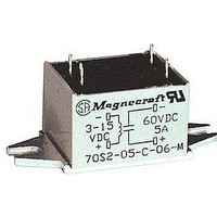
70S2-04-B-06-N Magnecraft / Schneider Electric, 70S2-04-B-06-N Datasheet - Page 15

70S2-04-B-06-N
Manufacturer Part Number
70S2-04-B-06-N
Description
Solid State Relays 6A/120VAC SPST-NO
Manufacturer
Magnecraft / Schneider Electric
Specifications of 70S2-04-B-06-N
Load Voltage Rating
140 V
Load Current Rating
6 A
Relay Type
Solid State
Termination Style
Solder Leads
Control Voltage Range
3VDC To 30VDC
Operating Voltage Range
24VAC To 140VAC
Load Current
6A
Isolation Voltage
4000VAC
Control Voltage Type
DC
Relay Terminals
Blade
Load Voltage Max
140VAC
Application
Ideal for tight designs, wide choice of design options, input isolated from output, reduced current surged for most loads, excellent transient protection
Brand/series
70S2 Series
Contact Form
SPST-NO
Current, Rating
6 A
Current, Surge
60, 150 A
Dielectric Strength
3000 V (RMS)
Dimensions
2.2 in. L x 1 in. W x 0.864 in. H
Function
Zero-Switching
Mounting Type
Panel
Standards
UL, CSA
Termination
Screw
Voltage, Control
30 VDC
Voltage, Rating
140 VAC
Lead Free Status / RoHS Status
Lead free / RoHS Compliant
Lead Free Status / RoHS Status
Lead free / RoHS Compliant, Lead free / RoHS Compliant
4/42
General Specifications (@ 25° C)
Output Characteristics
Number and type of Contacts
Switching Device
Current Rating
Switching voltage
Switching Type
Maximum Rate of Rise Off State Voltage (dv/dt)
Min. Load current to maintain on
Non-Repetitive Surge Current (1 cycle)
Max. Off state leakage current (rms)
Typical On State Voltage Drop (rms)
Minimum Peak Blocking Voltage
Input Characteristics
Voltage Range
Must Release Voltage
Typical Input Current @ 5VDC or 240VAC
Max. Reverse Control Voltage
Performance Characteristics
Operating time (response time)
Dielectric strength
Environment
Product certifications
Ambient air temperature
around the device
Miscellaneous Characteristics
Thermal Resistance (Junction to Case)
Weight
Mounting Screw Torque
File No. E258297
UL Recognized
70S2 Series Solid State Relays/H and L Style
Mounting
Panel
Maximum Continuous Current vs. Ambient Temperature
On
Off
Terminals to Chassis
Input to Output
Standard version
Storage
Operation
(UL 508)
Output
Terminals
8
7
6
5
4
3
2
1
STYLE L, 6A
STYLE H, 2.5A
°C/W
g (oz)
Units
V/us
Nm
mA
mA
mA
ms
ms
°C
°C
A
A
V
V
V
V
V
V
V
V
Input Terminals
8….50 AC
-40…+125
-40…+100
70S2-04-D
Zero Cross
3….30 DC
2500 AC
2500 AC
SPST-NO
UR, CSA
22 (0.8)
200 AC
1.6 AC
1….17
1 DC
3 DC
Triac
300
2.5
8.3
8.3
3.5
1.0
75
60
3
M agne cr aft S olu tion Guide 1 0 5 A
25
20
15
10
5
8….50 AC
6….30 DC
-40…+125
-40…+100
70S2-05-D
Zero Cross
2500 AC
2500 AC
SPST-NO
UR, CSA
200 AC
22 (0.8)
1.6 AC
1….6
1 DC
3 DC
Triac
300
2.5
8.3
8.3
3.5
1.0
75
60
3
STYLE S, 25A
STYLE N & S, 12A
STYLE N & S, 6A


