DLP-245PA DLP Design Inc, DLP-245PA Datasheet
DLP-245PA
Specifications of DLP-245PA


Related parts for DLP-245PA


DLP-245PA Summary of contents
Page 1
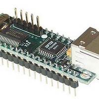
... USB / Microcontroller Module The DLP-245PA combines the same USB interface used in the DLP-USB245M module with a Microchip PIC microcontroller to form a rapid development tool. The 16F872 microcontroller is preprogrammed with basic functionality for accessing the port pins and can be reprogrammed with user hex code via a 5-pin header that is compatible with the DLP-FLASH device programmer (purchased separately) ...
Page 2
Royalty-free device drivers eliminate the need for USB driver development in most cases • USB bulk or isocronous data-transfer modes • Required 5V supply can be taken directly from the USB port or supplied by user electronics • USB ...
Page 3
... PC to communicate with the DLP-245PA as though it were connected to a COM (RS-232) port. In addition to VCP drivers, FTDI's D2XX direct drivers for Windows offer an alternative solution to the VCP drivers that allow application software to interface with the DLP-245PA using a DLL 3 ...
Page 4
... EEPROM WRITE UTILITY The DLP-245PA has the option to accept manufacturer-specific information that is written into the on-board 93C46 EEPROM. Parameters that can be programmed include the VID and the PID identifiers, the manufacturer's product string, and a serial number. ...
Page 5
... Download the DLL version of the device drivers from either dlpdesign.com or ftdichip.com. Unzip the drivers onto a blank floppy disk or into a folder on the hard drive. 2. The DLP-245PA can be configured to receive its operating power from the USB port or from user electronics. Pins 14, 15, and 16 allow for this configuration. (Refer to the Pinout Description in the next section for a detailed description of the DLP-245PA electrical interface ...
Page 6
... Features include the ability to read and write individual port pins as well as 8-bit port reads and writes. The firmware in the DLP-245PA also provides access to the 16F872’s A/D converter, EEPROM memory, and communications with digital temperature-sensing devices. Commands sent to the Token I/O firmware must adhere to a specific communications protocol. ...
Page 7
... The source code for the Token I/O firmware (developed for the CCS C compiler) is available as a free download from http://www.dlpdesign.com/usb/245pa.html. Example Visual C++ source code (for Windows 98/2000/XP) for communicating with the DLP-245PA via the Token I/O firmware is also available for download. The windows source code also contains the port pin definitions listed above ...
Page 8
... This function will select the source for the A/D conversion clock. (Refer to the datasheet for the 16F872 for a detailed explanation of the conversion clock.) Example: 0x3, 0xA8, 0x89, 0x81, 0xA3 – Sets all available A/D inputs on the DLP-245PA to analog mode (0x89) and selects Fosc/32 for 20MHz operation (0x81). 0xA9 – A/D Conversion Parameters: Analog Port Number – ...
Page 9
EEPROM Write Parameters: Address – Selects the zero-based address of the location in the 16F872’s internal EEPROM for writing. Data – Data to be written to the EEPROM. Returns: Undefined. Function: This function will write the selected location ...
Page 10
DS18S20 Read Data Parameters: Port Pin – Selects the microcontroller port pin on the 16F872 to be used for communication with the DS18S20 temperature sensor. Returns: 9 Bytes: The contents of the scratchpad memory in the DS18S20. Function: ...
Page 11
... TABLE 1: DLP-245PA PINOUT DESCRIPTION Pin # Description 1 GROUND 2 B0 (I/O) Port Pin E0 connected to the 16F872 microcontroller. A/D Channel 5. B4 (I/O) Port Pin A0 connected to the 16F872 microcontroller. A/D Channel (I/O) Port Pin A1 connected to the 16F872 microcontroller. A/D Channel 1. 5 UPRST (I/O) Port Pin A0 connected to the 16F872 microcontroller. ...
Page 12
... PORTVCC if the module powered by the USB port (typical configuration). 16 PORTVCC (Out) Power from USB port. Connect to EXTVCC if module powered by the USB port (typical configuration). 500mA is the maximum current available to the DLP-245PA and target electronics if the USB device is configured for high power. 17 DB7 (I/O) Line 7 of the data bus between the 16F872 and the FT245BM USB-FIFO ...
Page 13
... This product and its documentation are supplied on an as-is basis, and no warranty as to their suitability for any particular purpose is either made or implied. DLP Design will not accept any claim for damages whatsoever arising as a result of use or failure of this product. Your statutory rights are not affected ...
Page 14
GND 29 AGND 9 GND 17 GND Vdd 30 AVCC 3 VCC 26 VCC 13 VCC-IO 20 ...