DLP-IO16 DLP Design Inc, DLP-IO16 Datasheet
DLP-IO16
Specifications of DLP-IO16


Related parts for DLP-IO16


DLP-IO16 Summary of contents
Page 1
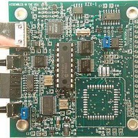
... PC application software that runs under Windows 98/2000 is available from dlpdesign.com as a free download that performs the Flash download process. The DLP-IO16 connects to the user’s hardware via 8 buffered digital inputs and 8 latched digital outputs. The digital outputs are implemented using an SN74HC374 and are specified to drive LSTTL loads each ...
Page 2
... INF files determine which set of drivers to load for each operating system version. Once loaded, the VCP drivers allow your application software, running on the host PC, to communicate with the DLP-IO16 as though it were connected to a COM (RS-232) port. ...
Page 3
... The application uses the DLL version of the device drivers. The HELP button can be clicked at any time to read a description of each control. This download application uses the “OpenEx” function that allows multiple DLP-IOx boards to be connected to the same well-organized manner. ...
Page 4
... EEPROM so that all of the EEPROM memory in the target would remain available for project use. The Connect function will attempt to initiate communications with the DLP-IO16 board using the serial number, the device description string or just the device number found in the Search edit box ...
Page 5
... Download the example software (DLPIO16X) from dlpdesign.com, unzip the package and place folder. 5. Connect the DLP-IO16 board to the PC via a standard, 6-foot USB cable. When prompted, select the folder where the DLL version of the device drivers were stored in step one. Windows will then complete the installation of the device drivers for the DLP-IO16 board. ...
Page 6
... Press the reset button on the DLP-IO16 board. This is the button closest to the USB connector. The LED next to the reset button will start to blink. Click on the Connect button in the download application. The LED will be on solid and the version string edit box will be blank ...
Page 7
... The External reset pin (pin 1) can be used by the target electronics to reset the USB interface on the DLP-IO16. The target microcontroller reset signal (pin 2) is made available such that target electronics can also be held in the reset state, if desired, during the firmware download process. ...
Page 8
... The DLP-IO16 takes all needed operational power from the host PC's USB port. When the host PC goes to Standby mode, the DLP-IO16 will also go to Standby mode after 3 milliseconds of no USB bus activity. If the 5-volt power for the DLP-IO16 board is supplied by the target electronics via the Digital I/O Interface connector (JP3) then the jumper at JP4 must be removed ...
Page 9
Mechanical Drawings Inches(millimeters) unless otherwise noted .50 typ. (12.7 typ.) 1.24 typ. .97 typ. (31.5 typ.) (24.7 typ.) Pin # Signal Type Description 1.17 typ. (29.7 typ.) .59 typ. (15.0 typ.) .95 typ. (24.1 typ.) .42 typ. .49 typ. (10.7 ...
Page 10
... Early versions of the DLP-IO16 boards may not meet the minimum current requirement in Standby mode. Please note that no software or documentation is shipped with the DLP-IO16. The latest version of the drivers, Windows application software and all documentation can be downloaded at any time from www.dlpdesign.com. ...