DLP-245SX DLP Design Inc, DLP-245SX Datasheet
DLP-245SX
Specifications of DLP-245SX


Related parts for DLP-245SX


DLP-245SX Summary of contents
Page 1
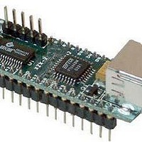
... USB / Microcontroller Module The DLP-245SX combines the same USB interface used in the DLP-USB245M module with a Ubicom SX28 microcontroller to form a rapid development tool. The SX28 microcontroller is preprogrammed with basic functionality for accessing the port pins and can be reprogrammed with user hex code via a 5-pin header (4 pins used) that is compatible with the DLP-FLASH device programmer (purchased separately) ...
Page 2
USB 1.1 and USB 2.0 compatible • USB VID, PID, serial number, and product description strings stored in on-board EEPROM • Virtual com port (VCP) drivers for: - Windows 98 and Windows Windows 2000/ME/XP - Windows ...
Page 3
... PC to communicate with the DLP-245SX as though it were connected to a COM (RS-232) port. In addition to VCP drivers, FTDI's D2XX direct drivers for Windows offer an alternative solution to the VCP drivers that allow application software to interface with the DLP-245SX using a DLL 3 ...
Page 4
... EEPROM WRITE UTILITY The DLP-245SX has the option to accept manufacturer-specific information that is written into the on-board 93C46 EEPROM. Parameters that can be programmed include the VID and the PID identifiers, the manufacturer's product string, and a serial number. ...
Page 5
... Note: The board will not operate until a power source has been selected as mentioned in Step 2. 3. Connect the DLP-245SX board to the PC via a standard A-B, 6-foot USB cable. This action initiates the loading of the USB drivers. When prompted, select the folder where the DLL version of the device drivers was stored in Step 1 ...
Page 6
... Features include the ability to read and write individual port pins as well as 8-bit port reads and writes. The firmware in the DLP-245SX also provides access to the on-board EEPROM memory, and communications with digital temperature-sensing devices. Commands sent to the Token I/O firmware must adhere to a specific communications protocol. ...
Page 7
... PIN_C4 0xC4, PIN_C5 0xC5, PIN_C6 0xC6, PIN_C7 0xC7, The source code for the Token I/O firmware (developed for the SnXC C compiler from Grich RC) is available as a free download upon purchase of the DLP-245SX. Example Visual C++ source code (for Windows 98/2000/XP) for communicating with the DLP-245SX via the Token I/O firmware is also available for download upon purchase ...
Page 8
TOKEN I/O COMMAND SET 0xA5 – Line In – Reads the state of a single port pin Parameters: Port – Select from available port pins (PIN_A3, PIN_B0, etc) Returns: 1 Byte: State of the port pin ( Function: ...
Page 9
DS18S20 Start Convert Parameters: Port Pin – Selects the microcontroller port pin on the SX28 to be used for communication with the DS18S20 temperature sensor. Returns: 1 Byte: A single byte indicating the result of trying to reset ...
Page 10
Reserved 0xAF – Loopback Parameters: Data byte – The byte of data to be looped back to the host. Returns: 1 Byte: The data byte written. Function: This function will echo the specified byte of data back to ...
Page 11
... TABLE 1: DLP-245SX PINOUT DESCRIPTION Pin # Description 1 Ground 2 A0 (I/O) Port Pin A0 connected to the SX28 microcontroller 3 A1 (I/O) Port Pin C2 connected to the SX28 microcontroller (I/O) Port Pin C3 connected to the SX28 microcontroller. 5 MCLR* (In) Can be used by an external device to reset the SX28. Can be left disconnected if not used ...
Page 12
... PORTVCC if the module powered by the USB port (typical configuration). 16 PORTVCC (Out) Power from USB port. Connect to EXTVCC if module powered by the USB port (typical configuration). 500mA is the maximum current available to the DLP-245SX and target electronics if the USB device is configured for high power. 17 DB7 (I/O) Line 7 of the data bus between the SX28 and the FT245BM USB-FIFO ...
Page 13
... This product and its documentation are supplied on an as-is basis, and no warranty as to their suitability for any particular purpose is either made or implied. DLP Design will not accept any claim for damages whatsoever arising as a result of use or failure of this product. Your statutory rights are not affected ...
Page 14
GND 29 AGND 9 GND 17 GND 28 MCLR VSS VDD 14 4 VSS VDD 30 AVCC 3 VCC 26 VCC 13 VCC-IO ...