CRD5463PM Cirrus Logic Inc, CRD5463PM Datasheet - Page 5
CRD5463PM
Manufacturer Part Number
CRD5463PM
Description
Power Management Modules & Development Tools Ref Design for Power Meter/Monitor
Manufacturer
Cirrus Logic Inc
Datasheet
1.CRD5463PM.pdf
(20 pages)
Specifications of CRD5463PM
Interface Type
SPI, UART, USB
Maximum Operating Temperature
+ 85 C
Operating Supply Voltage
90 VAC to 260 VAC
Product
Power Management Development Tools
For Use With/related Products
CS5463
Lead Free Status / RoHS Status
Lead free / RoHS Compliant


CRD5463PM
2.5 ATtiny2313 Microcontroller
In addition to the CS5463 on the daughter board, an Atmel™ ATtiny2313 microcontroller is used to initial-
ize the CS5463, convert the SPI into UART, and provide nonvolatile memory for the calibrations.
The ATtiny2313 is an MCU with SPI and UART interfaces, 2 kB Flash program memory and 128 bytes
EEPROM data memory. The MCU acts as a communication bridge between the CS5463’s SPI interface
and the UART of the UART-to-USB converter. The EEPROM data memory is used to store calibration
information.
The hardware connections between the ATtiny2313 and the CS5463 are RESET, SCLK, CS, SDI, SDO,
INT (interrupt), and connection-configurable clock signals. Through the population of the 0 ohms resistor
R15 or R16, the clock source can be shared between the CS5463 and the ATtimy2313. In the current
version of the CRD5463PM, the CS5463 and ATtiny2313 are configured to use their own clock sources.
The CS5463 uses a 4.096 MHz crystal and the ATtiny2313 uses its internal 8 MHz R-C oscillator.
On the daughter board, connector J4 is provided for programming and debugging the ATtiny2313 MCU.
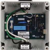
WARNING
High Voltage Hazard
The signal ground for the daughter board is the power line.
DO NOT CONNECT ANY DEBUGGING OR PROGRAMMING TOOLS TO THE J4 CONNECTOR WHEN
AC LINE POWER IS CONNECTED.
Please consult with Cirrus Logic engineering if re-programming the MCU is desired.
For more detailed information of ATtiny 2313, please refer to the ATtiny2313 datasheet.
2.6 Isolated UART
Because the CRD5463PM uses non-isolated components as the current and voltage sensors, the signal
ground of the CS5463 and MCU is the live connection to the main power. However, the signal ground of
the PC USB port is normally chassis ground or earth ground. The electrical isolation must be fulfilled on
the UART communication interface to allow the CRD5463PM to be connected to a PC through a USB
cable without short-circuit and safety problems. The CRD5463PM uses 2 opto-couplers to isolate the
UART interface. The isolation rating is 5300 V RMS.
2.7 UART-USB Interface- FT232R
A USB-to-UART interface IC, FT232R, is used on the main board to interface the CRD to a PC as a virtual
COM port through the USB connection.
3. SOFTWARE CONTROL
The CRD5463PM comes with GUI software and a USB cable to link the CRD to a PC. The GUI was de-
veloped with Lab Windows™/CVI™, a software development package from National Instruments Corpo-
ration. The GUI software is available for download on the Cirrus Logic web site at:
http://www.cirrus.com/industrialsoftware
®
The software was designed to run under Windows 2000™ or Windows XP
operating system.
DS805RD2
5
Related parts for CRD5463PM
Image
Part Number
Description
Manufacturer
Datasheet
Request
R

Part Number:
Description:
Development Kit
Manufacturer:
Cirrus Logic Inc
Datasheet:
Part Number:
Description:
Development Kit
Manufacturer:
Cirrus Logic Inc
Datasheet:


Part Number:
Description:
High-efficiency PFC + Fluorescent Lamp Driver Reference Design
Manufacturer:
Cirrus Logic Inc
Datasheet:
Part Number:
Description:
Development Kit
Manufacturer:
Cirrus Logic Inc
Datasheet:
Part Number:
Description:
Development Kit
Manufacturer:
Cirrus Logic Inc
Datasheet:

Part Number:
Description:
Development Kit
Manufacturer:
Cirrus Logic Inc
Datasheet:
Part Number:
Description:
Development Kit
Manufacturer:
Cirrus Logic Inc
Datasheet:
Part Number:
Description:
Development Kit
Manufacturer:
Cirrus Logic Inc
Datasheet:
Part Number:
Description:
Development Kit
Manufacturer:
Cirrus Logic Inc
Datasheet:
Part Number:
Description:
Audio Modules & Development Tools EvalBd 30W Qd Hlf- Brdg Dig Amp Pwr Stg
Manufacturer:
Cirrus Logic Inc
Datasheet:

Part Number:
Description:
EVALUATION BOARD FOR CS8427
Manufacturer:
Cirrus Logic Inc
Datasheet:

Part Number:
Description:
BOARD EVAL FOR CS8416 RCVR
Manufacturer:
Cirrus Logic Inc
Datasheet:

Part Number:
Description:
EVALUATION BOARD FOR CS8420
Manufacturer:
Cirrus Logic Inc
Datasheet:

Part Number:
Description:
KIT DEVELOPMENT EP9315 ARM9
Manufacturer:
Cirrus Logic Inc
Datasheet: