Electrical Output ...................................................................................................................................................................................... 2-bit quadrature code
Resolution ...........................................................................................................................................................................8 to 64 pulses per revolution (PPR)
Supply Voltage (VCC) .................................................................................................................................................................................5.0 VDC ± 0.25 VDC
Supply Current (ICC) ....................................................................................................................................................................................... 26 mA maximum
Output Voltage
Output Current I(SINK), per Channel ............................................................................................................................................................... 25 mA minimum
Rise/Fall Time ....................................................................................................................................................................................................... 200 ns typical
Power Dissipation ........................................................................................................................................................................................ 167 mW maximum
Pulse Width (per Channel) .....................................................................................................................................................................................180 °e typical
Phase Angle (Channel A Leads Channel B, Clockwise Rotation) ..........................................................................................................................90 °e ± 45 °e
Insulation Resistance @ 500 VDC .....................................................................................................................................................1,000 megohms minimum
Operating RPM ...................................................................................................................................................................................................120 maximum
Switch Power Rating .............................................................................................................................................12 VDC / 20 mA (600 ohms maximum load)
Switch Contact Resistance ........................................................................................................................................................................200 ohms maximum
Operating Temperature Range @ 5.0 VDC .......................................................................................................................-40 °C to +70 °C (-40 °F to +158 °F)
Storage Temperature Range ........................................................................................................................................... -55 ºC to +125 ºC (-67 °F to +257 °F)
Vibration ..............................................................................................................................................................................................................................15 G
Shock ..................................................................................................................................................................................................................................50 G
Humidity ..................................................................................................................................................................... MIL-STD-202, Method 103, Condition B
Flammability ............................................................................................................................................................................................Conforms to UL 94HB
IP Rating ...........................................................................................................................................................................................................................IP 54**
Mechanical Angle ............................................................................................................................................................................................360 ° Continuous
Torque
Rotational Life
Switch Life .......................................................................................................................................................................................................... 100,000 cycles
Switch Actuation Force
Switch Travel
Shaft Radial Play ..........................................................................................................................................................................................0.005 in. maximum
Shaft Axial Structural Strength ......................................................................................................................................................................... 35 lbs. minimum
Mounting Torque ..........................................................................................................................................................................2.0 N-m (18 lb.-in.) maximum
Terminals ....................................................................................................................................................................................................... Sn plated PC pins
Soldering Condition
Mounting Hardware
Marking ................................................................................................. Manufacturer’s symbol, model number, product code, terminal style and date code
Standard Packaging ........................................................................................................................................................ Anti-static plastic tube (25 pcs./tube)
**When device is mounted by normal mounting means.
*RoHS Directive 2002/95/EC Jan 27, 2003 including Annex.
Specifi cations are subject to change without notice.
Customers should verify actual device performance in their specifi c applications.
Electrical Characteristics
Environmental Characteristics
Mechanical Characteristics
Materials and Finishes
Low (VCE(sat)), per Channel ..................................................................................................................................... 800 mV maximum at I(SINK) = 25 mA
High (VO(HI)), per Channel ....................................................................................................................................... 4.0 VDC minimum @ VCC = 4.75 VDC
Starting/Running ...............................................................................................................................................................1.06 N-cm (1.5 oz.-in.) maximum
Detent ....................................................................................................................................................................................... 1.2 N-cm (1.7 oz.-in.) typical
Non-detent (@ 30 RPM) ........................................................................................................................................1,000,000 cycles (2,000,000 revolutions)
With detent (@ 30 RPM) ..............................................................................................................................................100,000 cycles (200,000 revolutions)
Standard ......................................................................................................................................................................................... 250 gm (8.82 oz.) typical
High Force .................................................................................................................................................................................... 850 gm (29.98 oz.) typical
Standard ......................................................................................................................................................................................................... 0.04 in. typical
High Force .................................................................................................................................................................................................... 0.025 in. typical
Manual Soldering ................................................................................................................... 96.5Sn/3.0Ag/0.5Cu solid wire or no-clean rosin cored wire
Wave Soldering ............................................................................................................................................ 96.5Sn/3.0Ag/0.5Cu solder with no-clean fl ux
Wash processes ...................................................................................................................................................................................... Not recommended
Nut ..............................................................................................................................Black annodized brass, hex (metric)/Nickel-plated brass, hex (SAE)
Lockwasher ........................................................................................................................................................... Nickel-plated spring steel, internal tooth
Features
■
■
■
■
■
■
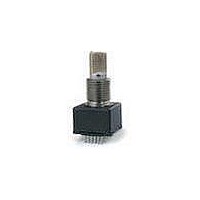
EM14 - 14 mm Rotary Optical Encoder w/Switch
Lead free
HCMOS, CMOS and TTL compatible
Compact package size
High rotational cycle life
Standard or high force push switch option
Optional detent
370 °C (700 °F) max. for 3 seconds
260 °C (500 °F) max. for 5 seconds