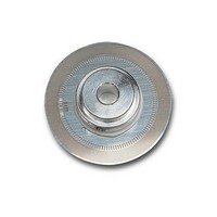
HEDS-5140-H14 Avago Technologies US Inc., HEDS-5140-H14 Datasheet - Page 5

HEDS-5140-H14
Manufacturer Part Number
HEDS-5140-H14
Description
Metal CW,28mm,3Ch,400CPR,5mm
Manufacturer
Avago Technologies US Inc.
Series
HEDSr
Datasheet
1.HEDM-5120B06.pdf
(13 pages)
Specifications of HEDS-5140-H14
Pulses Per Revolution
400 CPR
Number Of Channels
3
Supply Voltage
5 V
Operating Temperature Range
- 40 C to + 100 C
Product
Optical
Size / Dimension
28 mm
Accessory Type
Codewheel
Lead Free Status / Rohs Status
Lead free / RoHS Compliant
For Use With/related Products
HEDS-914x Series
For Use With
HEDS-9140#H00 - ENCODER MODULE 3CH 400CPR
Assembly Instructions Using Avago Technologies Assembly Tools
Instructions
1. Place codewheel on shaft.
2. Set codewheel height:
Figure 2. Alignment Tool is Used to Set Height of Codewheel.
5
GAP SETTING SHIM
a. Place the correct gap setting tool (per Ordering
b. Push codewheel down against gap setting shim.
c. Tighten codewheel setscrew.
IMAGE SIDE OF CODEWHEEL
Information Table) on motor base, flush up against
the motor shaft as shown in Figure 2. The shim has
two different size steps. Choose the one that most
closely matches the width of the codewheel boss.
The shim should not contact the codewheel boss.
The codewheel is now at the proper height.
HEDS-51X0 fig 2
CODEWHEEL
MODULE SIDE A
MODULE SIDE B
3. Insert mounting screws through module and thread
4. Slide the HEDS-8905 or HEDS-8906 centering tool
5. While holding alignment tool in place, tighten screws
6. Remove alignment tools.
Figure 3. Alignment Tool is Placed over Shaft and onto Codewheel Hub.
Alignment Tool Pins Mate with Aligning Recesses on Module.
CENTERING TOOL
CODEWHEEL
into the motor base. Do not tighten screws.
over codewheel hub and onto module as shown in
Figure 3. The pins of the alignment tool should fit
snugly inside the alignment recesses of the module.
down to secure module.
ALIGNING RECESSES
MODULE SIDE A
MODULE SIDE B


