CSTCR4M00G53Z-R0 Murata Electronics North America, CSTCR4M00G53Z-R0 Datasheet - Page 21
CSTCR4M00G53Z-R0
Manufacturer Part Number
CSTCR4M00G53Z-R0
Description
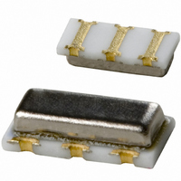
RESONATOR 4.00MHZ CERAMIC INDUST
Manufacturer
Murata Electronics North America
Series
CERALOCK®, CSTCRr
Type
Ceramicr
Specifications of CSTCR4M00G53Z-R0
Frequency
4MHz
Features
Built in Capacitor
Frequency Stability
±0.2%
Frequency Tolerance
±0.5%
Impedance
60 Ohm
Capacitance
15pF
Operating Temperature
-40°C ~ 125°C
Mounting Type
Surface Mount
Package / Case
3-SMD, Non-Standard
Size / Dimension
0.177" L x 0.079" W (4.50mm x 2.00mm)
Height
0.045" (1.15mm)
Lead Free Status / RoHS Status
Lead free / RoHS Compliant
Other names
490-1217-2
Available stocks
Company
Part Number
Manufacturer
Quantity
Price
Company:

Part Number:
CSTCR4M00G53Z-R0
Manufacturer:
MURATA
Quantity:
240 000


Note
• This PDF catalog is downloaded from the website of Murata Manufacturing co., ltd. Therefore, it’s specifications are subject to change or our products in it may be discontinued without advance notice. Please check with our
• This PDF catalog has only typical specifications because there is no space for detailed specifications. Therefore, please approve our product specifications or transact the approval sheet for product specifications before ordering.
sales representatives or product engineers before ordering.
As described in Chapter 2, the most common oscillation
circuit with CERALOCK
circuit with CERALOCK
varies with the application and the IC being used, etc.
Although the basic configuration of the circuit is the
same as that of a quartz crystal, the difference in
mechanical Q results in the difference of the circuit
constant.
This chapter briefly describes the characteristics of the
oscillation circuit and gives some typical examples.
It is becoming more common to configure the oscillation
circuit with a digital IC, and the simplest way to use an
inverter gate.
Fig. 4-1 shows the configuration of a basic oscillation
circuit with a C-MOS inverter.
INV. 1 works as an inverter amplifier of the oscillation
circuit. INV. 2 acts to shape the waveform and also acts
as a buffer for the connection of a frequency counter.
The feedback resistance Rf provides negative feedback
around the inverter in order to put it in the linear
region, so the oscillation will start, when power is
applied.
If the value of Rf is too large, and if the insulation
resistance of the input inverter is accidentally
decreased, oscillation will stop due to the loss of loop
gain. Also, if Rf is too great, noise from other circuits
can be introduced into the oscillation circuit.
Obviously, if Rf is too small, loop gain will be low. An Rf
of 1MΩ is generally used with a ceramic resonator.
Damping resistor Rd provides loose coupling between
the inverter and the feedback circuit and decreases the
loading on the inverter, thus saving energy.
In addition, the damping resistor stabilizes the phase of
the feedback circuit and provides a means of reducing
the gain in the high frequency area, thus preventing the
possibility of spurious oscillation.
Load capacitance C
180°.
The proper selected value depends on the application,
the IC used, and the frequency. If C
are too low, the loop gain in the high frequency is
increased, which in turn increases the probability of
spurious oscillation.
This is particularly likely around 4 to 5 MHz, where the
thickness vibration mode lies, as shown in Fig. 2-5 when
using kHz band resonator.
1. Cautions for Designing Oscillation Circuits
4
Applications of Typical Oscillation Circuits
L1
and C
®
®
. The design of the circuit
is to replace L of a Colpitts
L2
provide the phase lag of
L1
and C
L2
values
Fig. 4-1 Basic Oscillation Circuit with C-MOS Inverter
INV.1
C
L1
IC
X
Rd
C
INV.2
L2
IC
C
L1
V
DD
, C
Rd : Dumping Resistor
IC : 1/6CD4069UBE(RCA)
L2
X : CERALOCK
Output
: External Capacitance
®
19
P17E.pdf
10.8.3
4
Related parts for CSTCR4M00G53Z-R0
Image
Part Number
Description
Manufacturer
Datasheet
Request
R

Part Number:
Description:
BUZZER PIEZO 25VP-P SMD
Manufacturer:
Murata Electronics North America

Part Number:
Description:
CAP 4-ARRAY 680PF 100V X7R 1206
Manufacturer:
Murata Electronics North America
Datasheet:
Part Number:
Description:
CAP 4-ARRAY 1000PF 100V X7R 1206
Manufacturer:
Murata Electronics North America
Datasheet:
Part Number:
Description:
CAP 4-ARRAY 1800PF 100V X7R 1206
Manufacturer:
Murata Electronics North America
Datasheet:
Part Number:
Description:
CAP 4-ARRAY 68000PF 16V X7R 1206
Manufacturer:
Murata Electronics North America
Datasheet:

Part Number:
Description:
CAP CER 1000PF 50V 10% X7R 0402
Manufacturer:
Murata Electronics North America
Datasheet:
Part Number:
Description:
CAP CER 10000PF 16V 10% X7R 0402
Manufacturer:
Murata Electronics North America
Datasheet:

Part Number:
Description:
CAP 5.5-25PF 2.5X3.2MM SMD
Manufacturer:
Murata Electronics North America
Datasheet:

Part Number:
Description:
CAP 4.5-20PF 2.5X3.2MM SMD
Manufacturer:
Murata Electronics North America
Datasheet:

Part Number:
Description:
CAP 5.0-20PF 3.2X4.5MM SMD RED
Manufacturer:
Murata Electronics North America
Datasheet:

Part Number:
Description:
CAP 2.0-6.0PF 3.2X4.5MM SMD BLU
Manufacturer:
Murata Electronics North America
Datasheet:

Part Number:
Description:
CAP 1.4-3.0PF 3.2X4.5MM SMD BRN
Manufacturer:
Murata Electronics North America
Datasheet:

Part Number:
Description:
CAP 3.0-10PF 3.2X4.5MM SMD WHT
Manufacturer:
Murata Electronics North America
Datasheet:

Part Number:
Description:
CAP 2.0-6.0PF 4X4.5MM TOPADJ BLU
Manufacturer:
Murata Electronics North America
Datasheet:

Part Number:
Description:
CAP 8.5-40PF 4X4.5MM TOPADJ YEL
Manufacturer:
Murata Electronics North America
Datasheet: