NOTE: Pad layout guidelines per MIL-STD-275E
(printed wiring for electronic equipment).
Tolerances: xx ± 0.01" [± 0.25 mm]. xxx ± 0.005"
[± 0.12 mm].
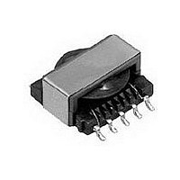
The underside of these components contains
metal and thus should not come into contact with
active circuit traces.
Document Number: 34066
Revision: 17-Apr-07
DIMENSIONS in inches [millimeters]
DESCRIPTION
MODEL
GLOBAL PART NUMBER
Pad Layout
Dimensional Outline
LPE
[2.54]
0.100
Typ.
Gapped and Ungapped, Custom Configurations Available
[1.47]
0.058
0.335 [8.51]
6562
SIZE
PRODUCT FAMILY
Max.
L
10
6
Reference Only
Foot print Diagram
INDUCTANCE VALUE
0.092 [2.34] Pad Dimensions
Typical, 10 places
[14.60]
[13.84]
[15.32]
0.575
0.545
0.603
P
[17.65]
0.695
Max.
1000 µH
Surface Mount Transformers/Inductors,
[0.71]
0.028
E
0.100 [2.54]
Typical
4 places
5
1
[15.39]
0.606
Max.
[0.71]
0.028
6
For technical questions, contact: magnetics@vishay.com
INDUCTANCE TOLERANCE
5
SIZE
± 30 %
ELECTRICAL SPECIFICATIONS
(Multiple winds are connected in parallel)
Inductance Range: 10 µH to 330 000 µH, measured at 0.10 V RMS
at 10 kHz without DC current, using an HP 4263A or HP 4284A
impedance analyzer
DC Resistance Range: 0.03 Ω to 53.7 Ω, measured at + 25 °C ± 5 °C
Rated Current Range: 3.00 amps to 0.06 amps
Dielectric Withstanding Voltage: 500 V RMS, 60 Hz, 5 seconds
* DC current that will create a maximum temperature rise of 30 °C when applied at + 25 °C
ambient. ** DC current that will typically reduce the initial inductance by 20 %.
UNGAPPED MODELS: Highest possible inductance with the lowest DCR and highest Q
capability. Beneficial in filter, impedance matching and line coupling devices.
GAPPED MODELS: Capable of handling large amounts of DC current, tighter inductance
tolerance with better temperature stability than ungapped models. Beneficial in DC to DC
converters or other circuits carrying DC currents or requiring inductance stability over a
temperature range.
6
STANDARD ELECTRICAL SPECIFICATIONS
MODEL
Ungapped Models
LPE-6562-221NA
LPE-6562-331NA
LPE-6562-471NA
LPE-6562-681NA
LPE-6562-102NA
LPE-6562-152NA
LPE-6562-222NA
LPE-6562-332NA
LPE-6562-472NA
LPE-6562-682NA
LPE-6562-103NA
LPE-6562-153NA
LPE-6562-223NA
LPE-6562-333NA
LPE-6562-473NA
LPE-6562-683NA
LPE-6562-104NA
LPE-6562-154NA
LPE-6562-224NA
LPE-6562-334NA
Gapped Models
LPE-6562-100MB
LPE-6562-150MB
LPE-6562-220MB
LPE-6562-330MB
LPE-6562-470MB
LPE-6562-680MB
LPE-6562-101MB
LPE-6562-151MB
LPE-6562-221MB
LPE-6562-331MB
LPE-6562-471MB
LPE-6562-681MB
LPE-6562-102MB
LPE-6562-152MB
LPE-6562-222MB
LPE-6562-332MB
LPE-6562-472MB
2
PACKAGE
E
CORE
CODE
150 000
220 000
330 000
A
10 000
15 000
22 000
33 000
47 000
68 000
10 000
1000
1500
2200
3300
4700
6800
1000
1500
2200
3300
4700
IND.
(µH)
220
330
470
680
100
150
220
330
470
680
10
15
22
33
47
68
R
PACKAGE CODE
± 30 %
± 30 %
± 30 %
± 30 %
± 30 %
± 30 %
± 30 %
± 30 %
± 30 %
± 30 %
± 30 %
± 30 %
± 30 %
± 30 %
± 30 %
± 30 %
± 30 %
± 30 %
± 30 %
± 30 %
± 20 %
± 20 %
± 20 %
± 20 %
± 20 %
± 20 %
± 20 %
± 20 %
± 20 %
± 20 %
± 20 %
± 20 %
± 20 %
± 20 %
± 20 %
± 20 %
± 20 %
TOL.
IND.
ER
1
INDUCTANCE
SCHEMATIC
LETTER
VALUE
A
A
A
A
A
A
A
A
A
A
A
A
A
A
A
A
A
A
A
A
B
B
B
B
D
C
D
E
E
E
E
E
E
E
E
E
E
0
JEDEC LEAD (Pb)-FREE STANDARD
MAX.
DCR
0.28
0.34
0.40
0.48
0.59
0.72
0.87
1.07
1.27
1.53
1.86
2.27
8.67
10.6
12.7
15.2
18.5
37.7
45.6
53.7
0.03
0.04
0.05
0.08
0.12
0.19
0.29
0.45
0.54
0.84
1.24
1.89
2.91
4.50
6.90
10.4
15.7
(Ω)
2
DC CURRENT
MAX. RATED*
TOL.
N
(Amps)
0.90
0.81
0.74
0.67
0.61
0.55
0.50
0.45
0.41
0.38
0.34
0.31
0.16
0.14
0.13
0.12
0.11
0.08
0.07
0.06
3.09
2.79
2.26
1.81
1.48
1.20
0.98
0.78
0.71
0.57
0.47
0.38
0.31
0.25
0.20
0.16
0.13
e2
Vishay Dale
CORE
LPE-6562
T
www.vishay.com
SATURATING
CURRENT**
(Amps)
5.055
4.160
3.460
2.840
2.390
1.990
1.650
1.350
1.115
0.912
0.765
0.637
0.526
0.430
0.355
0.290
0.243
N/A
N/A
N/A
N/A
N/A
N/A
N/A
N/A
N/A
N/A
N/A
N/A
N/A
N/A
N/A
N/A
N/A
N/A
N/A
RoHS
COMPLIANT
159