36MB100A Vishay, 36MB100A Datasheet - Page 2
36MB100A
Manufacturer Part Number
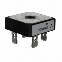
36MB100A
Description
RECTIFIER BRIDGE 1000V 35A D-34A
Manufacturer
Vishay
Datasheet
1.36MB160A.pdf
(6 pages)
Specifications of 36MB100A
Voltage - Peak Reverse (max)
1000V
Current - Dc Forward (if)
35A
Diode Type
Single Phase
Speed
Standard Recovery >500ns, > 200mA (Io)
Mounting Type
QC Terminal
Package / Case
D-34
Product
Single Phase Bridge
Peak Reverse Voltage
1000 V
Max Surge Current
500 A
Forward Voltage Drop
1.14 V
Maximum Reverse Leakage Current
10 mA
Power Dissipation
0.35 W
Maximum Operating Temperature
+ 150 C
Length
28.5 mm
Width
28.5 mm
Height
9.8 mm
Mounting Style
Stud
Minimum Operating Temperature
- 55 C
Phase Type
Single Phase
Number Of Elements
1
Peak Rep Rev Volt
1kV
Peak Non-repetitive Surge Current (max)
500A
Avg. Forward Curr (max)
35A
Rev Curr
10uA
Operating Temp Range
-55C to 150C
Pin Count
4
Mounting
Screw
Operating Temperature Classification
Military
Lead Free Status / RoHS Status
Lead free / RoHS Compliant
Reverse Recovery Time (trr)
-
Lead Free Status / Rohs Status
Compliant
Other names
*36MB100A
VS-36MB100A
VS-36MB100A
VS36MB100A
VS36MB100A
VS-36MB100A
VS-36MB100A
VS36MB100A
VS36MB100A
Available stocks
Company
Part Number
Manufacturer
Quantity
Price
Company:

Part Number:
36MB100A
Manufacturer:
IXYS
Quantity:
387
Part Number:
36MB100A
Manufacturer:
IR
Quantity:
20 000


MB High Voltage Series
Vishay High Power Products
www.vishay.com
2
FORWARD CONDUCTION
PARAMETER
Maximum DC output current
at case temperature
Maximum peak, one cycle
non-repetitive forward current
Maximum I
Maximum I
Low level of threshold voltage
High level of threshold voltage
Low level forward slope resistance
High level forward slope resistance
Maximum forward voltage drop
Maximum DC reverse current per diode
RMS isolation voltage base plate
THERMAL AND MECHANICAL SPECIFICATIONS
PARAMETER
Junction and storage
temperature range
Maximum thermal resistance,
junction to case per bridge
Maximum thermal resistance,
case to heatsink
Mounting torque ± 10 %
Approximate weight
2
2
t for fusing
√t for fusing
SYMBOL
T
R
R
J
, T
thCS
thJC
Stg
For technical questions, contact: ind-modules@vishay.com
SYMBOL
V
V
V
I
I
F(TO)1
F(TO)2
V
I
RRM
FSM
I
2
r
r
ISOL
I
2
FM
O
t1
t2
√t
t
Mounting surface, smooth, flat and greased
Bridge to heatsink
(Power Modules), 25 A/35 A
Single Phase Bridge
Resistive or inductive load
Capacitive load
t = 10 ms
t = 8.3 ms
t = 10 ms
t = 8.3 ms
t = 10 ms
t = 8.3 ms
t = 10 ms
t = 8.3 ms
I
0.1 ≤ t
(16.7 % x π x I
T
(I > π x I
(16.7 % x π x I
T
(I > π x I
T
(26MB)
T
(36MB)
T
f = 50 Hz, t = 1 s
2
J
J
J
J
J
t for time t
maximum
maximum
= 25 °C, I
= 25 °C, I
= 25 °C, at V
TEST CONDITIONS
x
≤ 10 ms, V
F(AV)
F(AV)
x
FM
FM
), T
), T
TEST CONDITIONS
= I
F(AV)
F(AV)
= 40 Apk
= 55 Apk
2
RRM
No voltage
reapplied
100 % V
reapplied
No voltage
reapplied
100 % V
reapplied
J
J
√t x √t
maximum
maximum
RRM
< I < π x I
< I < π x I
x
= 0 V
;
RRM
RRM
F(AV)
F(AV)
),
),
Initial T
T
t
p
J
= 400 µs
maximum
J
=
26MB-A
1.7
- 55 to 150
26MB-A
2700
0.70
0.75
1.25
400
420
335
350
790
725
560
512
5.6
7.0
6.4
25
20
65
10
0.2
2.0
20
36MB-A
Document Number: 93564
1.35
36MB-A
1130
1030
2700
11.3
0.74
0.79
475
500
400
420
800
730
5.5
5.2
1.3
Revision: 17-Jun-08
35
28
60
10
UNITS
K/W
UNITS
Nm
kA
°C
g
A
mΩ
µA
°C
A
A
V
V
V
2
2
√s
s
Related parts for 36MB100A
Image
Part Number
Description
Manufacturer
Datasheet
Request
R

Part Number:
Description:
357-036-542-201 CARDEDGE 36POS DL .156 BLK LOPRO
Manufacturer:
Vishay
Datasheet:
Part Number:
Description:
357-036-542-201 CARDEDGE 36POS DL .156 BLK LOPRO
Manufacturer:
Vishay
Datasheet:
Part Number:
Description:
357-036-542-201 CARDEDGE 36POS DL .156 BLK LOPRO
Manufacturer:
Vishay
Datasheet:
Part Number:
Description:
357-036-542-201 CARDEDGE 36POS DL .156 BLK LOPRO
Manufacturer:
Vishay
Datasheet:
Part Number:
Description:
357-036-542-201 CARDEDGE 36POS DL .156 BLK LOPRO
Manufacturer:
Vishay
Datasheet:
Part Number:
Description:
357-036-542-201 CARDEDGE 36POS DL .156 BLK LOPRO
Manufacturer:
Vishay
Datasheet:
Part Number:
Description:
357-036-542-201 CARDEDGE 36POS DL .156 BLK LOPRO
Manufacturer:
Vishay
Datasheet:
Part Number:
Description:
357-036-542-201 CARDEDGE 36POS DL .156 BLK LOPRO
Manufacturer:
Vishay
Datasheet:
Part Number:
Description:
357-036-542-201 CARDEDGE 36POS DL .156 BLK LOPRO
Manufacturer:
Vishay
Datasheet:
Part Number:
Description:
357-036-542-201 CARDEDGE 36POS DL .156 BLK LOPRO
Manufacturer:
Vishay
Datasheet:
Part Number:
Description:
357-036-542-201 CARDEDGE 36POS DL .156 BLK LOPRO
Manufacturer:
Vishay
Datasheet:
Part Number:
Description:
357-036-542-201 CARDEDGE 36POS DL .156 BLK LOPRO
Manufacturer:
Vishay
Datasheet:
Part Number:
Description:
357-036-542-201 CARDEDGE 36POS DL .156 BLK LOPRO
Manufacturer:
Vishay
Datasheet:
Part Number:
Description:
357-036-542-201 CARDEDGE 36POS DL .156 BLK LOPRO
Manufacturer:
Vishay
Datasheet:
Part Number:
Description:
357-036-542-201 CARDEDGE 36POS DL .156 BLK LOPRO
Manufacturer:
Vishay
Datasheet: