GBPC6005/1 Vishay, GBPC6005/1 Datasheet

RECTIFIER BRIDGE 6A 50V GBPC6

GBPC6005/1

Manufacturer Part Number
GBPC6005/1
Description
RECTIFIER BRIDGE 6A 50V GBPC6
Manufacturer
Vishay
Datasheet

Specifications of GBPC6005/1

Diode Type
Single Phase
Package / Case
GBPC6
Voltage - Peak Reverse (max)
50V
Current - Dc Forward (if)
3A
Speed
Standard Recovery >500ns, > 200mA (Io)
Mounting Type
Through Hole
Product
Single Phase Bridge
Peak Reverse Voltage
50 V
Maximum Rms Reverse Voltage
35 V
Forward Continuous Current
6 A
Max Surge Current
175 A
Forward Voltage Drop
1 V
Maximum Reverse Leakage Current
5 uA
Maximum Operating Temperature
+ 150 C
Length
16 mm
Width
16 mm
Height
5.08 mm
Mounting Style
Through Hole
Minimum Operating Temperature
- 55 C
Peak Reflow Compatible (260 C)
No
Current Rating
6A
Leaded Process Compatible
No
Forward Voltage
50V
Forward Current If
6A
Lead Free Status / RoHS Status
Contains lead / RoHS non-compliant
Reverse Recovery Time (trr)
-
Lead Free Status / RoHS Status
Contains lead / RoHS non-compliant, Contains lead / RoHS non-compliant
Other names
GBPC6005
GBPC6005
GBPC6005/1
GBPC6005/1GI
Notes:
(1) Bolt down on heat-sink with silicone thermal compound between bridge and mounting surface for maximum heat transfer with #6 screw
(2) Unit mounted on 5.5 x 6.0 x 0.11" thick (14 x 15 x 0.3 cm) aluminum plate
(3) Unit mounted on P.C.B. at 0.375" (9.5 mm) lead length with 0.5 x 0.5" (12 x 12 mm) copper pads
Document Number: 88613
Revision: 15-Apr-08
PRIMARY CHARACTERISTICS
MAXIMUM RATINGS (T
PARAMETER
Maximum repetitive peak reverse voltage
Maximum RMS bridge input voltage
Maximum DC blocking voltage
Maximum average forward
rectified output current at
Peak forward surge current single sine-wave
superimposed on rated load
Rating for fusing (t < 8.3 ms)
Operating junction and storage temperature range
T
V
I
J
I
F(AV)
FSM
RRM
V
I
max.
R
F
Glass Passivated Single-Phase Bridge Rectifier
Case Style GBPC6
PDD-Americas@vishay.com, PDD-Asia@vishay.com, PDD-Europe@vishay.com
~
For technical questions within your region, please contact one of the following:
T
T
~
A
C
A
= 40 °C
= 50 °C
= 25 °C unless otherwise noted)
50 V to 1000 V
~
(3)
(1)(2)
150 °C
175 A
1.0 V
5 µA
6 A
SYMBOL
T
J
V
V
I
I
V
, T
F(AV)
FSM
RRM
RMS
I
DC
2
t
STG
~
GBPC
6005
50
35
50
FEATURES
TYPICAL APPLICATIONS
General purpose use in ac-to-dc bridge full wave
rectification for power supply, home appliances, office
equipment, industrial automation applications.
MECHANICAL DATA
Case: GBPC6
Epoxy meets UL 94V-0 flammability rating
Terminals: Silver plated leads, solderable per
J-STD-002 and JESD22-B102
E4 suffix for consumer grade
Polarity: As marked, positive lead by belevled corner
Mounting Torque: 10 cm-kg (8.8 inches-lbs) max.
Recommended Torque: 5.7 cm-kg (5 inches-lbs)
• UL recognition file number E54214
• Ideal for printed circuit boards
• Typical I
• High surge current capability
• High case dielectric strength 1500 V
• Solder dip 260 °C, 40 s
• Component in accordance to RoHS 2002/95/EC
GBPC
601
100
100
70
and WEEE 2002/96/EC
GBPC
GBPC6005 thru GBPC610
Vishay General Semiconductor
602
200
140
200
R
less than 0.5 µA
- 55 to + 150
GBPC
604
400
280
400
175
127
6.0
3.0
GBPC
606
600
420
600
GBPC
608
800
560
800
RMS
www.vishay.com
GBPC
1000
1000
610
700
UNIT
e4
A
°C
V
V
V
A
A
2
s
1

Related parts for GBPC6005/1

GBPC6005/1 Summary of contents

Page 1

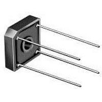
... Unit mounted on P.C.B. at 0.375" (9.5 mm) lead length with 0.5 x 0.5" ( mm) copper pads Document Number: 88613 For technical questions within your region, please contact one of the following: Revision: 15-Apr-08 PDD-Americas@vishay.com, PDD-Asia@vishay.com, PDD-Europe@vishay.com FEATURES • UL recognition file number E54214 • Ideal for printed circuit boards • ...

Page 2

... GBPC6005 thru GBPC610 Vishay General Semiconductor ELECTRICAL CHARACTERISTICS (T PARAMETER Maximum instantaneous forward voltage drop per diode Maximum DC reverse current at rated DC blocking voltage per diode Typical junction capacitance per diode THERMAL CHARACTERISTICS (T PARAMETER (1) Typical thermal resistance Notes: (1) Bolt down on heat-sink with silicone thermal compound between bridge and mounting surface for maximum heat transfer with #6 screw (2) Unit mounted on 5.5 x 6.0 x 0.11" ...

Page 3

... Percent of Rated Peak Reverse Voltage (%) Figure 4. Typical Reverse Leakage Characteristics Per Diode PACKAGE OUTLINE DIMENSIONS in inches (millimeters) Document Number: 88613 For technical questions within your region, please contact one of the following: Revision: 15-Apr-08 PDD-Americas@vishay.com, PDD-Asia@vishay.com, PDD-Europe@vishay.com 1000 100 10 1.4 1.6 1.8 ...

Page 4

... Vishay product could result in personal injury or death. Customers using or selling Vishay products not expressly indicated for use in such applications their own risk and agree to fully indemnify and hold Vishay and its distributors harmless from and against any and all claims, liabilities, expenses and damages arising or resulting in connection with such use or sale, including attorneys fees, even if such claim alleges that Vishay or its distributor was negligent regarding the design or manufacture of the part ...

Related keywords