P11VYN1KA201KA Vishay, P11VYN1KA201KA Datasheet
P11VYN1KA201KA
Specifications of P11VYN1KA201KA


Related parts for P11VYN1KA201KA

P11VYN1KA201KA Summary of contents
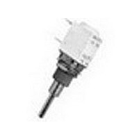
Page 1
... End Resistance (Typical) Independent Linearity (Typical) Linear Law Insulation Resistance Dielectric Strength Attenuation Mechanical Rotational Life * Consult Vishay Sfernice for other ohmic values MECHANICAL SPECIFICATIONS PA11 AND P11 Mechanical Travel: Operating Torque (typical): Single and Dual Assemblies (1/8") dia. Shafts 6 mm (1/4" ...
Page 2
... CIRCUIT DIAGRAM 7.2 (0.284) a Ø 8.5 (1) (0.335 ( SWITCH: MOMENTARY PUSH OR PUSH-PUSH Wrench 10 or 3/8 For technical questions, contact: sfer@vishay.com See also: Application notes P11, PA11 Vishay Sfernice - 12.7 (0.500 (0.157) W-W2 W1 12.7 (0.500) (0.500) ...
Page 3
... For technical questions, contact: sfer@vishay.com See also: Application notes dimensions inches ± (0.01) 1/8” 1/4” 1/8” 1/4” 1/4” 3/8” 3/8” 1/2” ...
Page 4
... Interlinearity is measured between 2 pot modules, over the attenuation. The interlinearity or interconformity is expressed as a percentage of the total applied voltage : Or in decibels by comparison between outputs V1 and V2 For technical questions, contact: sfer@vishay.com See also: Application notes P11, PA11 Vishay Sfernice ± ΔV max linearity conformity = ...
Page 5
... Switch actuation (CW direction) reverses these positions. RSIF SINGLE POLE CHANGEOVER In full CW position, the contact is made between 1 and 2 and open between 1 and 3. Switch actuation (CCW direction) reverses these positions. For technical questions, contact: sfer@vishay.com See also: Application notes PA11 P11 CERMET CONDUCTIVE PLASTIC ± ...
Page 6
... CC-3, 0-3, and 77-3. See dimensional drawings on second page of this data sheet CUSTOM SHAFTS When special shafts are required - flat, threaded ends, special shaft lengths, etc. a drawing is required. For technical questions, contact: sfer@vishay.com See also: Application notes P11, PA11 Vishay Sfernice RS - RSI 62.5 VA υ ...
Page 7
... See data sheet document No. 51021 MARKING 8 ± 0.5 POTENTIOMETER MODULE VISHAY logo, nominal ohmic value (Ω, kΩ, MΩ), two stars Fig. 9 identify PA11 version, tolerance variation law, manufacturing date (four digits), "3" for the lead 3. SWITCH MODULE Version, manufacturing date (four digits), "c" for common lead ...
Page 8
... non linear laws -cermet Conductive plastic linear law 470 W to 500 k W non-linear laws ± ± ± For technical questions, contact: sfer@vishay.com See also: Application notes P11, PA11 Vishay Sfernice P : FROM MOUNTING FACE All panel sealing versions have a Dia. Length bushing of 8mm dia ...
Page 9
... SAP PART NUMBERING GUIDELINES STYLE NB MODEL OF MODULES See the end of this data book for conversion tables www.vishay.com 102 Conductive Plastic Elements (PA11 BUSHING PEG SHAFT For technical questions, contact: sfer@vishay.com See also: Application notes LEADS OHMIC VALUE/TOL/LAW OR SPECIAL Document Number: 51031 Revision: 23-Aug- ...
Page 10
... Information contained herein is intended to provide a product description only. No license, express or implied, by estoppel or otherwise, to any intellectual property rights is granted by this document. Except as provided in Vishay's terms and conditions of sale for such products, Vishay assumes no liability whatsoever, and disclaims any express or implied warranty, relating to sale and/or use of Vishay products including liability or warranties relating to fitness for a particular purpose, merchantability, or infringement of any patent, copyright, or other intellectual property right ...