AC164130-2 Microchip Technology, AC164130-2 Datasheet - Page 14
AC164130-2
Manufacturer Part Number
AC164130-2
Description
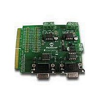
MCU, MPU & DSP Development Tools CAN/LIN PICtail Plus Daughter Board
Manufacturer
Microchip Technology
Series
PICtail™ Plusr
Datasheet
1.AC164130-2.pdf
(32 pages)
Specifications of AC164130-2
Processor To Be Evaluated
PIC18
Product
Microcontroller Modules
Main Purpose
Interface, CAN, ECAN LIN
Embedded
No
Utilized Ic / Part
MCP2021, MCP2551
Primary Attributes
2 CAN and 2 LIN Transceivers, 4 Socketed IC's
Secondary Attributes
Requires Explorer 16 Board
Lead Free Status / RoHS Status
Lead free / RoHS Compliant
Available stocks
Company
Part Number
Manufacturer
Quantity
Price
Company:

Part Number:
AC164130-2
Manufacturer:
Microchip Technology
Quantity:
135


CAN/LIN/J2602 PICtail
DS70319B-page 14
For PIC18 devices, the pinout for the LIN1 and LIN2 modules can be different. The
jumpers J4, J8, J13 and J14 are for choosing between these pinouts. For the specific
pinout that is necessary for the PIC18 that is used, refer to that device’s data sheet. For
PIC24 and dsPIC33 devices, make sure to leave the J4, J8, J13 and J14 jumpers
disconnected. Otherwise, these connections can disrupt LIN communications.
For detailed information on the MCP2021-500 LIN Transceiver, refer to Microchip Data
Sheet MCP202X “LIN Transceiver with Voltage Regulator” (DS22018).
1.2.2
The CAN/LIN/J2602 PICtail™ (Plus) Daughter Board connects two high-speed CAN
transceivers to ECAN modules on the control device on the development board. The
CAN transceivers convert the differential signal on the CAN bus to a digital signal for
the ECAN module. It also converts the ECAN output digital signal to a differential signal
for the CAN bus.
All PIC18 devices have one CAN module, which is connected to the CAN1 transceiver
(U3). For some PIC18s, there is an optional alternate pinout for the CAN module that
is chosen by an internal MUX. This alternate pinout is connected to the CAN2 trans-
ceiver (U4). Depending on the number of pins the device has, this alternate pinout has
two options. These two options are chosen by the two jumpers (J15 and J16). For
detailed information on the CAN pinout options for the PIC18, refer to that device’s data
sheet. Also, the alternate CAN pinout for some PIC18s is the same as the LIN1 pinout.
If this is the case, LIN1 and CAN communications cannot be used simultaneously. For
PIC24 and dsPIC33 devices, make sure to leave J15 and J16 disconnected.
Otherwise, these connections can disrupt CAN communications.
In Sleep mode, the CAN transmitter is turned off, and the receiver operates at a lower
current level. The control device monitors CAN activity and switches the transceiver
back to normal operation when needed.
For detailed information on the MCP2551 High-Speed CAN Transceiver, refer to
Microchip Data Sheet MCP2551 “High-Speed CAN Transceiver” (DS21667).
CAN Operation
™
(Plus) Daughter Board User’s Guide
2011 Microchip Technology Inc.
Related parts for AC164130-2
Image
Part Number
Description
Manufacturer
Datasheet
Request
R

Part Number:
Description:
Fuses 16A 415V AC/250V DC
Manufacturer:
Apex Tool Group (Formerly Cooper Tools)

Part Number:
Description:
Manufacturer:
Microchip Technology Inc.
Datasheet:
Part Number:
Description:
Manufacturer:
Microchip Technology Inc.
Datasheet:
Part Number:
Description:
Manufacturer:
Microchip Technology Inc.
Datasheet:
Part Number:
Description:
Manufacturer:
Microchip Technology Inc.
Datasheet:
Part Number:
Description:
Manufacturer:
Microchip Technology Inc.
Datasheet:
Part Number:
Description:
Manufacturer:
Microchip Technology Inc.
Datasheet:
Part Number:
Description:
Manufacturer:
Microchip Technology Inc.
Datasheet:
Part Number:
Description:
Manufacturer:
Microchip Technology Inc.
Datasheet: