ZICM2410P2-2-SN CEL, ZICM2410P2-2-SN Datasheet
ZICM2410P2-2-SN
Specifications of ZICM2410P2-2-SN


Related parts for ZICM2410P2-2-SN


ZICM2410P2-2-SN Summary of contents
Page 1
... Part Number Order Number ZICM2410P0-1 ZICM2410P0-1-SN MeshConnect™ ZICM2410P0-1C Module ZICM2410P0-1C-SN ZICM2410P0-KIT2-1 ZICM2410P2-2 ZICM2410P2-2-SN MeshConnect™ ZICM2410P2-1C Extended Range Module ZICM2410P2-1C-SN ZICM2410P2-KIT1-1 The information in this document is subject to change without notice, please confirm data is current Document No: 0007-00-07-00-000 (Issue D) Date Published: February 8, 2011 DATA SHEET MeshConnect™ ...
Page 2
... For more detail information regarding MeshConnect Development Kits, refer to the respective development kit user guides documents. (Available at CEL’s website http://www.cel.com) Order Number Description ZICM2410P0-KIT2-1 +6 dBm Engineering Development Kit ZICM2410P2-KIT1-1 Evaluation board for +20 dBm module Extended Range Module 16 MHz XTAL PWR Reg ANT MeshConnect™ ...
Page 3
TABLE OF CONTENTS Introduction and Overview Description.............................................................................................................................................................................................. Features.................................................................................................................................................................................................. Applications............................................................................................................................................................................................ Ordering Information............................................................................................................................................................................. Module Block Diagram........................................................................................................................................................................... Development Kit..................................................................................................................................................................................... System Level Function Transceiver IC......................................................................................................................................................................................... Modes of Operation (TX, RX, Sleep)...................................................................................................................................................... Power Amplifier....................................................................................................................................................................................... Interface.................................................................................................................................................................................................. Software Tools........................................................................................................................................................................................ Electrical Specification Absolute Maximum Ratings................................................................................................................................................................... Recommended (Operating Condition).................................................................................................................................................. ...
Page 4
... Premium (1 Mbps), for networks looking for increased throughput. The device provides numerous general-purpose I/O pins, peripheral functions such as timers and UARTs and is one of the first devices to provide an embedded Voice CODEC. CEL provides its customers with the IEEE 802.15.4 stack as part of the software library. Also available are the hardware & software tools required to develop custom applications. ...
Page 5
... To further improve performance, a ground plane may be placed on the host board under the module the antenna. The installation of an uninterrupted ground plane on a layer directly beneath the module will also allow you to run traces under this layer. CEL can provide assistance with your PCB layout. MODES OF OPERATION There are three power down modes in the IC ...
Page 6
... The ZICM2410P0 MeshConnect module does not incorporate an external Power Amplifier and therefore the RF output port is connected directly (through matching components) to the RF antenna. As CEL’s IC IEEE 802.15.4 transceiver already offers the industry’s best link budget at 103 dB, even without an external PA the MeshConnect can maintain wireless connection over long distance (2,000 ft line-of-sight) ...
Page 7
SOFTWARE TOOLS (Continued) PACKET ANALYZER AND WIRELESS NETWORK ANALYZER • Packet Analyzer monitors traffic over a wireless network channel by capturing RF packet data in real-time. • Packet Analyzer requires the Wireless Network Analyzer to “sniff” the RF packets. • ...
Page 8
ABSOLUTE MAXIMUM RATINGS Description Power Supply Voltage (Vcc) Voltage on any digital pin Input RF Level Storage Temperature Reflow Soldering Temperature Note: Exceeding the maximum ratings may cause permanent damage to the module or devices. RECOMMENDED (OPERATING CONDITIONS) Description Operating ...
Page 9
PIN SIGNALS I/O PORT CONFIGURATION MeshConnect module has 56 edge I/O interfaces for connection to the user’s host board. The MeshConnect Module Dimensions shows the layout of the 56 edge castellations. MeshConnect I/O PIN ASSIGNMENTS MeshConnect™ MeshConnect™ Pin Extended Range ...
Page 10
MeshConnect I/O PIN ASSIGNMENTS MeshConnect™ MeshConnect™ Pin Extended Range # Module Module 28 P3_5 P3_5 29 P3_4 P3_4 30 GND GND 31 P3_3 P3_3 32 P3_2 P3_2 33 GND GND 34 P3_1 P3_1 35 P3_0 P3_0 36 GND GND 37 ...
Page 11
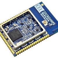
MODULE DIMENSIONS MeshConnect™ Module / MeshConnect™ Extended Range Module w/U.FL Connector for external antenna Module ZICM2410P0 0000 000 Pin 1 C21 C7 C7B R10 C11 L3 C24 C13 C5B L4 R1 C14 ...
Page 12
MODULE LAND FOOTPRINT Note: Unless otherwise specified. Dimensions are in Inches [mm]. MeshConnect™ Module Series Page 12 ...
Page 13
... See IPC-A-610 "Acceptability of Electronic Assemblies, section 8.2.4 Castellated Terminations.” Cleaning In general, cleaning the populated modules is strongly discouraged. Residuals under the module cannot be easily removed with any cleaning process. • Cleaning with water can lead to capillary effects where water is absorbed into the gap between the host board and the module ...
Page 14
... This device must accept any interference received, including interference that may cause undesired operation. Warning (Part 15.21) Changes or modifications not expressly approved by CEL could void the user's authority to operate the equipment Separation Distance To comply with FCC/IC RF exposure limits for general population / uncontrolled exposure, the antenna(s) used for this transmitter must be installed to provide a separation distance of at least 20 cm from all persons and must not be co-located or operating in conjunction with any other antenna or transmitter ...
Page 15
... Shipment The MeshConnect Modules are delivered in trays of 28. Handling The MeshConnect Modules are designed and packaged to be processed in an automated assembly line. Warning The MeshConnect Modules contain highly sensitive electronic circuitry. Handling without proper ESD protection may destroy or damage the module permanently. ...
Page 16
... CEL does not assume any liability for infringement of patents, copyrights or other intellectual property rights of third parties by or arising from the use of CEL products listed in this document or any other liability arising from the use of such products. No license, express, implied or otherwise, is granted under any patents, copyrights or other intellectual property rights of CEL or others. • ...