2KBP005 Vishay, 2KBP005 Datasheet - Page 2
2KBP005
Manufacturer Part Number
2KBP005
Description
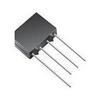
Bridge Rectifiers 50 Volt 2.0 Amp
Manufacturer
Vishay
Specifications of 2KBP005
Product
Single Phase Bridge
Peak Reverse Voltage
50 V
Maximum Rms Reverse Voltage
20 V
Max Surge Current
63 A
Forward Voltage Drop
1 V
Maximum Reverse Leakage Current
10 uA
Maximum Operating Temperature
+ 150 C
Length
17.5 mm
Width
6.8 mm
Height
15 mm
Mounting Style
Through Hole
Minimum Operating Temperature
- 40 C
Package / Case
D-44
Phase Type
Single Phase
Number Of Elements
1
Peak Rep Rev Volt
50V
Rms Voltage (max)
20V
Peak Non-repetitive Surge Current (max)
63A
Avg. Forward Curr (max)
2A
Rev Curr
10uA
Forward Voltage
1V
Package Type
D-44
Operating Temp Range
-40C to 150C
Pin Count
4
Mounting
Through Hole
Operating Temperature Classification
Automotive
Lead Free Status / RoHS Status
Lead free / RoHS Compliant
Available stocks
Company
Part Number
Manufacturer
Quantity
Price
Company:

Part Number:
2KBP005M
Manufacturer:
FSC
Quantity:
1 200


2KBP Series
Vishay High Power Products
www.vishay.com
2
FORWARD CONDUCTION
PARAMETER
Maximum DC output current
Maximum peak one cycle,
non-repetitive surge current
Maximum I
Maximum I
Maximum peak forward voltage per diode
Typical peak reverse leakage
current per diode
Operating frequency range
THERMAL AND MECHANICAL SPECIFICATIONS
PARAMETER
Operating junction and storage temperature range
Approximate weight
2.2
2.0
1.8
1.6
1.4
1.2
1.0
0.8
0.6
0.4
0.2
2
2
Maximum Allowable Ambient Temperature (°C)
0
t capability for fusing
√t capability for fusing
0
Fig. 1 - Ambient Temperature Ratings
20
Capacitive load
40
60
Resistive, inductive load
80
100
For technical questions, contact: ind-modules@vishay.com
SYMBOL
120
I
V
I
FSM
I
I
RM
I
2
FM
O
f
2
√t
t
140
Rectifier Bridge, 2 A
T
T
t = 10 ms, 20 ms
t = 8.3 ms, 16.7 ms
t = 10 ms
t = 8.3 ms
t = 10 ms
t = 8.3 ms
t = 0.1 to 10 ms, no voltage reapplied
I
T
T
160
FM
A
A
J
J
Single Phase
= 25 °C, 100 % V
= 150 °C, 100 % V
= 50 °C, resistive or inductive load
= 50 °C, capacitive load
= 1 A, T
SYMBOL
T
J
, T
J
Stg
= 25 °C
TEST CONDITIONS
RRM
RRM
Following any rated load
condition and with rated V
reapplied
100 % V
reapplied
No voltage
reapplied
70
60
50
40
30
20
10
RRM
0
10
- 40 to 150
-2
VALUES
Fig. 2 - Non-Repetitive Surge Ratings
0.14
Initial T
T
4
J
maximum
Pulse Train Duration (s)
J
10
=
RRM
-1
From any rated
load condition
40 to 1000
VALUES
Document Number: 93562
255
2.0
1.8
1.0
1.0
60
63
18
16
26
23
10
1
Revision: 17-Jun-08
UNITS
oz.
°C
g
UNITS
A
A
mA
µA
Hz
2
A
A
V
2
√s
10
s
Related parts for 2KBP005
Image
Part Number
Description
Manufacturer
Datasheet
Request
R

Part Number:
Description:
357-036-542-201 CARDEDGE 36POS DL .156 BLK LOPRO
Manufacturer:
Vishay
Datasheet:
Part Number:
Description:
357-036-542-201 CARDEDGE 36POS DL .156 BLK LOPRO
Manufacturer:
Vishay
Datasheet:
Part Number:
Description:
357-036-542-201 CARDEDGE 36POS DL .156 BLK LOPRO
Manufacturer:
Vishay
Datasheet:
Part Number:
Description:
357-036-542-201 CARDEDGE 36POS DL .156 BLK LOPRO
Manufacturer:
Vishay
Datasheet:
Part Number:
Description:
357-036-542-201 CARDEDGE 36POS DL .156 BLK LOPRO
Manufacturer:
Vishay
Datasheet:
Part Number:
Description:
357-036-542-201 CARDEDGE 36POS DL .156 BLK LOPRO
Manufacturer:
Vishay
Datasheet:
Part Number:
Description:
357-036-542-201 CARDEDGE 36POS DL .156 BLK LOPRO
Manufacturer:
Vishay
Datasheet:
Part Number:
Description:
357-036-542-201 CARDEDGE 36POS DL .156 BLK LOPRO
Manufacturer:
Vishay
Datasheet:
Part Number:
Description:
357-036-542-201 CARDEDGE 36POS DL .156 BLK LOPRO
Manufacturer:
Vishay
Datasheet:
Part Number:
Description:
357-036-542-201 CARDEDGE 36POS DL .156 BLK LOPRO
Manufacturer:
Vishay
Datasheet:
Part Number:
Description:
357-036-542-201 CARDEDGE 36POS DL .156 BLK LOPRO
Manufacturer:
Vishay
Datasheet:
Part Number:
Description:
357-036-542-201 CARDEDGE 36POS DL .156 BLK LOPRO
Manufacturer:
Vishay
Datasheet:
Part Number:
Description:
357-036-542-201 CARDEDGE 36POS DL .156 BLK LOPRO
Manufacturer:
Vishay
Datasheet:
Part Number:
Description:
357-036-542-201 CARDEDGE 36POS DL .156 BLK LOPRO
Manufacturer:
Vishay
Datasheet:
Part Number:
Description:
357-036-542-201 CARDEDGE 36POS DL .156 BLK LOPRO
Manufacturer:
Vishay
Datasheet: