25MT060WFAPBF Vishay, 25MT060WFAPBF Datasheet - Page 2
25MT060WFAPBF
Manufacturer Part Number
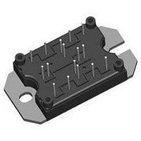
25MT060WFAPBF
Description
Bridge Rectifiers 600 Volt 50 Amp Full Bridge
Manufacturer
Vishay
Datasheet
1.25MT060WFAPBF.pdf
(8 pages)
Specifications of 25MT060WFAPBF
Package / Case
MTP
Maximum Operating Temperature
+ 150 C
Length
44.5 mm
Width
33 mm
Height
16 mm
Mounting Style
Screw
Minimum Operating Temperature
- 40 C
Power Dissipation Pd
250W
Collector Emitter Voltage V(br)ceo
600V
Continuous Collector Current Ic
50A
Leaded Process Compatible
Yes
Collector Emitter Saturation Voltage Vce(sat)
3.25V
Lead Free Status / RoHS Status
Lead free / RoHS Compliant


25MT060WFAPbF
Vishay High Power Products
Note
(1)
www.vishay.com
2
ELECTRICAL SPECIFICATIONS (T
PARAMETER
Collector to emitter breakdown voltage
Temperature coefficient of breakdown voltage ΔV
Collector to emitter saturation voltage
Gate threshold voltage
Temperature coefficient of threshold voltage
Transconductance
Zero gate voltage collector current
Gate to emitter leakage current
Diode forward voltage drop
SWITCHING CHARACTERISTICS (T
PARAMETER
Total gate charge (turn-on)
Gate to emitter charge (turn-on)
Gate to collector charge (turn-on)
Turn-on switching loss
Turn-off switching loss
Total switching loss
Turn-on switching loss
Turn-off switching loss
Total switching loss
Input capacitance
Output capacitance
Reverse transfer capacitance
Diode reverse recovery time
Diode peak reverse current
Diode Recovery charge
Diode peak rate of fall of
recovery during t
I
CES
includes also opposite leg overall leakage
b
For technical questions, contact:
J
ΔV
J
= 25 °C unless otherwise noted)
SYMBOL
SYMBOL
dI
(Warp Speed IGBT), 50 A
V
(BR)CES
I
= 25 °C unless otherwise specified)
"Full Bridge" IGBT MTP
V
GE(th)
V
CES
(rec)M
(BR)CES
C
I
V
C
C
CE(on)
Q
Q
E
E
E
E
GE(th)
E
E
GES
Q
Q
g
t
I
oes
FM
res
on
off
tot
on
off
tot
ies
rr
rr
fe
ge
gc
rr
g
(1)
/ΔT
/dt
/ΔT
J
J
V
V
V
V
V
V
V
V
V
V
V
V
I
I
I
I
I
V
V
R
V
V
R
V
V
V
V
f = 1.0 MHz
V
I
dI/dt = 200 A/μs
C
C
C
C
C
C
GE
GE
GE
GE
GE
GE
CE
CE
CE
GE
GE
GE
CC
GE
CC
GE
CC
GE
GE
CC
R
g
g
= 25 A;
= 25 A
= 50 A
= 25 A; T
= 50 A; T
= 25 A
= 5 Ω, I
= 5 Ω, I
= 200 V;
= V
= V
= 100 V, I
= 0 V, I
= 0 V, I
= 15 V, I
= 15 V, I
= 15 V, I
= 15 V, I
= 0 V, V
= 0 V, V
= ± 20 V
= 480 V
= 15 V
= 480 V
= ± 15 V, T
= 480 V
= ± 15 V, T
= 0 V
= 30 V
GE
GE
TEST CONDITIONS
TEST CONDITIONS
indmodules@vishay.com
, I
, I
C
C
C
C
C
J
J
C
CE
CE
= 25 A
= 25 A
C
C
C
C
= 150 °C
= 250 μA (25 °C to 125 °C)
= 150 °C
= 250 μA
= 4 mA (25 °C to 125 °C)
= 250 μA
C
= 25 A
= 50 A
= 25 A, T
= 50 A, T
= 600 V, T
= 600 V, T
J
J
= 25 A, PW = 80 μs
= 25 °C
= 125 °C
J
J
= 150 °C
= 150 °C
J
J
= 25 °C
= 150 °C
MIN.
MIN.
600
3
-
-
-
-
-
-
-
-
-
-
-
-
-
-
-
-
-
-
-
-
-
-
-
-
-
-
-
-
-
-
Document Number: 94539
TYP.
3610
TYP.
+ 0.6
0.13
0.42
0.55
0.39
0.49
0.88
2.22
2.43
1.65
2.08
1.36
1.57
1.19
1.48
- 17
175
714
112
250
4.5
27
71
58
50
43
-
-
-
-
-
Revision: 01-Mar-09
MAX.
MAX.
± 250
5415
1071
0.20
0.62
0.82
0.59
0.74
1.32
3.14
3.25
1.93
2.45
1.64
1.93
1.42
1.80
250
263
107
10
41
87
6
-
-
-
-
-
-
-
-
UNITS
UNITS
mV/°C
V/°C
A/μs
mA
mJ
μA
nA
nC
nC
pF
ns
V
V
S
V
A
Related parts for 25MT060WFAPBF
Image
Part Number
Description
Manufacturer
Datasheet
Request
R

Part Number:
Description:
357-036-542-201 CARDEDGE 36POS DL .156 BLK LOPRO
Manufacturer:
Vishay
Datasheet:
Part Number:
Description:
357-036-542-201 CARDEDGE 36POS DL .156 BLK LOPRO
Manufacturer:
Vishay
Datasheet:
Part Number:
Description:
357-036-542-201 CARDEDGE 36POS DL .156 BLK LOPRO
Manufacturer:
Vishay
Datasheet:
Part Number:
Description:
357-036-542-201 CARDEDGE 36POS DL .156 BLK LOPRO
Manufacturer:
Vishay
Datasheet:
Part Number:
Description:
357-036-542-201 CARDEDGE 36POS DL .156 BLK LOPRO
Manufacturer:
Vishay
Datasheet:
Part Number:
Description:
357-036-542-201 CARDEDGE 36POS DL .156 BLK LOPRO
Manufacturer:
Vishay
Datasheet:
Part Number:
Description:
357-036-542-201 CARDEDGE 36POS DL .156 BLK LOPRO
Manufacturer:
Vishay
Datasheet:
Part Number:
Description:
357-036-542-201 CARDEDGE 36POS DL .156 BLK LOPRO
Manufacturer:
Vishay
Datasheet:
Part Number:
Description:
357-036-542-201 CARDEDGE 36POS DL .156 BLK LOPRO
Manufacturer:
Vishay
Datasheet:
Part Number:
Description:
357-036-542-201 CARDEDGE 36POS DL .156 BLK LOPRO
Manufacturer:
Vishay
Datasheet:
Part Number:
Description:
357-036-542-201 CARDEDGE 36POS DL .156 BLK LOPRO
Manufacturer:
Vishay
Datasheet:
Part Number:
Description:
357-036-542-201 CARDEDGE 36POS DL .156 BLK LOPRO
Manufacturer:
Vishay
Datasheet:
Part Number:
Description:
357-036-542-201 CARDEDGE 36POS DL .156 BLK LOPRO
Manufacturer:
Vishay
Datasheet:
Part Number:
Description:
357-036-542-201 CARDEDGE 36POS DL .156 BLK LOPRO
Manufacturer:
Vishay
Datasheet:
Part Number:
Description:
357-036-542-201 CARDEDGE 36POS DL .156 BLK LOPRO
Manufacturer:
Vishay
Datasheet: