MS25183-20-4P Amphenol, MS25183-20-4P Datasheet - Page 62
MS25183-20-4P
Manufacturer Part Number
MS25183-20-4P
Description
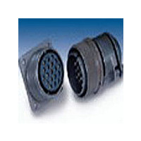
Circular MIL / Spec Connectors 4P SIZE 20 STRAIGHT PLUG PIN
Manufacturer
Amphenol
Type
MIL-DTL5015 Circularr
Series
MS Seriesr
Datasheet
1.CS3102C-20-27P-472.pdf
(73 pages)
Specifications of MS25183-20-4P
Contact Gender
PIN
Number Of Contacts
4POS
Shell Size / Insert Arrangement
20-4
Termination Method
Solder
Shell Plating
Cadmium
Body Orientation
Straight
Strain Relief
No
Contact Classification
4Signal
Operating Temp Range
-55C to 125C
Mil Type
MIL-DTL-5015
Product Type
Connectors
Lead Free Status / RoHS Status
Not Compliant


Assembly Instructions
for 10-305200 & 10-74900 cable clamps
The 10-305200 cable clamp and MS3420A sleeve illustrated are used only on
the rear of MS-A or C type connectors. The 10-74900 clamp and grommet
assembly can only be used on special feed-thru applications involving dummy
shells, part numbers 10-37090 and 10-113276.
10-305200 Cable Clamp & MS3420A Sleeve
10-74900 Clamp and Grommet Assembly
4
3
3
2
1. Clamping Nut
2. Tapered Sleeve
3. Grommet
1. Clamping Nut
2. Tapered Sleeve
3. Gland
4. Reducing or
2
Telescoping Sleeve
1
1
61
ASSEMBLY
Both clamps are shipped from the factory with lubricant
conforming to MIL-G-3278. Remove any dirt or foreign
material from components with ethyl alcohol and relubri-
cate as outlined under “lubrication.” Place the clamping
nut (1) on the wire bundle or cable with the threads facing
toward the connector or dummy shell. Position the
tapered sleeve (2) on the bundle or cable with the narrow
portion toward the clamping nut (1). Next install either the
gland (3) used with the 10-305200 clamp or thread each
wire through the grommet (3) used with the 10-74900
clamp. Dependent on the application, the wire bundle or
cable is fed through the dummy shell, or the wire ends
are soldered to the connector contacts. Move the compo-
nents forward in the reverse order of preliminary assem-
bly. (In applications where grommets (3) are used, seat
the grommet against the undercut in the back shell
before bringing the tapered sleeve (2) up against it).
Insure proper positioning of glands (3) or grommets (3),
tapered sleeves (2) and clamping nuts (1). Tighten the
clamp using a strap wrench until a metal to metal seat is
obtained.
Related parts for MS25183-20-4P
Image
Part Number
Description
Manufacturer
Datasheet
Request
R


Part Number:
Description:
Cable Specification: PU CABLE, UL20549 24AWG*8C+AD,OD= 6.0mm
Manufacturer:
Amphenol