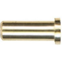
0355-0-15-01-02-01-10-0 Mill-Max Manufacturing Corp., 0355-0-15-01-02-01-10-0 Datasheet

0355-0-15-01-02-01-10-0
Manufacturer Part Number
0355-0-15-01-02-01-10-0
Description
Circuit Board Hardware - PCB SOCKET PC SOLDER MT
Manufacturer
Mill-Max Manufacturing Corp.
Type
Contactr
Series
0355r
Datasheets
1.0355-0-15-01-02-27-10-0.pdf
(1 pages)
2.0355-0-15-01-02-27-10-0.pdf
(1 pages)
3.0355-0-15-01-02-01-10-0.pdf
(2 pages)
4.0355-0-15-01-02-01-10-0.pdf
(1 pages)
Specifications of 0355-0-15-01-02-01-10-0
Pitch (mm)
Not Requiredmm
Gender
RCP
Number Of Contacts
1POS
Number Of Contact Rows
Not Required
Mounting Style
Through Hole
Body Orientation
Straight
Contact Plating
Tin-Lead Over Nickel
Operating Temp Range
-55C to 125C
Termination Method
Solder
Current Rating (max)
8A
Contact Material
BeCu Alloy
Contact Resistance Max
10mOhm
Housing Material
Not Required
Housing Color
Not Required
Product Length (mm)
7.37mm
Product Depth (mm)
3mm
Connector Type
PCB Socket
No. Of Contacts
1
Contact Termination
Solder
Peak Reflow Compatible (260 C)
No
Leaded Process Compatible
No
Length
0.290" (7.37mm)
Inside Diameter
0.050" (1.27mm)
Hole Diameter
0.102" (2.59mm)
Flange Diameter
0.118" (3.00mm)
Mounting Type
Solder
Contact Finish
Tin-Lead
Contact Finish Thickness
200µin (5.08µm)
Lead Free Status / RoHS Status
Not Compliant
Lead Free Status / RoHS Status
Not Compliant, Lead free / RoHS Compliant
w w w. m i l l - m a x . c o m
BERYLLIUM COPPER Alloy 172, Heat Treated
BERYLLIUM NICKEL Alloy 360, Heat Treated
FOR .037-.043 DIAMETER PINS (
CONTACT MATERIAL:
FOR .037-.043 DIAMETER PINS (
CONTACT MATERIAL:
FOR .022-.042 DIAMETER PINS (
CONTACT MATERIAL:
BERYLLIUM COPPER Alloy 172, Heat Treated
6-FINGER, GROUP L (see page 214)
6-FINGER, GROUP L (see page 214)
4-FINGER, GROUP E (see page 214)
#18 CONTACT
#58 CONTACT
#36 CONTACT
δ=.004)
δ=.003)
δ=.022)
Insertion / Extraction Force Graphs
CONTACT DATA
The insertion/extraction/normal force characteristics above were derived using 30 microinch gold plated contact
and polished steel gauge pins having a bullet-shaped tip.
The curves represent typical average values; they are best used to compare the differences between similar size
contacts and to guide you in selecting one that is suitable for your application. Your results may vary, so for your
specification, we encourage you to obtain complimentary samples for your evaluation.
The insertion/extraction/normal force characteristics above were derived using 30 microinch gold plated contact
The curves represent typical average values; they are best used to compare the differences between similar size
The insertion/extraction/normal force characteristics above were derived using 30 microinch gold plated contact
and polished steel gauge pins having a bullet-shaped tip.
The curves represent typical average values; they are best used to compare the differences between similar size
contacts and to guide you in selecting one that is suitable for your application. Your results may vary, so for your
specification, we encourage you to obtain complimentary samples for your evaluation.
and polished steel gauge pins having a bullet-shaped tip.
contacts and to guide you in selecting one that is suitable for your application. Your results may vary, so for your
specification, we encourage you to obtain complimentary samples for your evaluation.
1000.0
1000.0
100.0
100.0
10.0
1000
10.0
100
10
223
INITIAL INSERTION FORCE
INSERTION FORCE 2nd CYCLE
EXTRACTION FORCE
INITIAL INSERTION FORCE
INSERTION FORCE 2nd CYCLE
EXTRACTION FORCE
MATING PIN DIAMETER (inches)
MATING PIN DIAMETER (inches)
MATING PIN DIAMETER (inches)
#58 CONTACT
#18 CONTACT
#36 CONTACT
OPERATING RANGE
OPERATING RANGE
OPERATING RANGE
INITIAL INSERTION FORCE
INSERTION FORCE 2nd CYCLE
EXTRACTION FORCE
( 5 1 6 - 9 2 2 - 6 0 0 0
PINS


