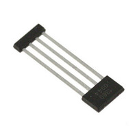
A1360LKTTN-T Allegro Microsystems Inc, A1360LKTTN-T Datasheet - Page 19

A1360LKTTN-T
Manufacturer Part Number
A1360LKTTN-T
Description
IC,HALL-EFFECT SENSOR,SINGLE-ENDED,BICMOS,SIP,4PIN,PLASTIC
Manufacturer
Allegro Microsystems Inc
Type
Linear - Unipolar, Bipolarr
Datasheet
1.A1360LKTTN-T.pdf
(25 pages)
Specifications of A1360LKTTN-T
Sensing Range
0.7mV/G ~ 1.4mV/G
Voltage - Supply
4.5 V ~ 5.5 V
Current - Supply
12mA
Current - Output (max)
10mA
Output Type
Analog, Ratiometric
Features
Programmable
Operating Temperature
-40°C ~ 150°C
Package / Case
4-SIP
Lead Free Status / RoHS Status
Lead free / RoHS Compliant
Other names
620-1233-2
A1360, A1361,
and A1362
Blow Mode
After the required value of the programmable parameter is
addressed using Try mode, its corresponding code can be blown
to make its value permanent. To do this, select the required
parameter register and the appropriate code. (See the Fuse Blow-
ing section. Recall that each bit of a desired code must be blown
individually before cycling the supply.) If the desired parameter
is in the first zone, enter the appropriate key-code combination
and then apply two high-level voltage pulses followed by an
additional blow pulse. If the desired parameter is in the second
Figure 6. Pulses to enter Try mode, zone 2. Example shown is
for addressing the Fine Quiescent Voltage Output register. After
addressing desired code, cycle the supply to reset the bit field or apply
a blow pulse to make the parameter value permanent.
Adjustable Bandwidth (50 kHz Maximum) and Analog Output
Low-Noise Programmable Linear Hall Effect Sensor ICs with
zone, enter the appropriate key-code combination and then apply
a single blow pulse on the VOUT pin. This is diagrammed as
follows:
Note: During a single blowing sequence, only one programmable
parameter in a single zone should be set at a time. After each
blow sequence the supply should be cycled before attempting to
blow additional bits.
Lock Mode
To lock the device, address the LOCK bit and apply a blow pulse
with C
2, code 4. After locking the device, no future programming of any
parameter is possible.
The lock sequence is:
Zone 1: V
V
Zone 2: V
Single Bit → V
V
→ V
PH
PH
BLOW
→ V
→ V
PM
→ V
PH
in place. The LOCK bit is located in zone 2, register
PH
PH
PH
→ Key → V
→ V
→ V
PM
PH
→ V
PH
PH
→ V
→ V
PH
115 Northeast Cutoff
1.508.853.5000; www.allegromicro.com
Allegro MicroSystems, Inc.
Worcester, Massachusetts 01615-0036 U.S.A.
PH
PH
PM
→ Code for Single Bit → V
→ Key → V
→ V
PM
→V
PH
PH
→ Code for
→ V
PM
→ V
PH
PM
→
19


