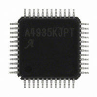
A4935KJPTR-T Allegro Microsystems Inc, A4935KJPTR-T Datasheet - Page 11

A4935KJPTR-T
Manufacturer Part Number
A4935KJPTR-T
Description
AUTO THREE-PHASE MOSFET PREDRIVER
Manufacturer
Allegro Microsystems Inc
Datasheet
1.A4935KJPTR-T.pdf
(24 pages)
Specifications of A4935KJPTR-T
Configuration
3 Phase Bridge
Input Type
PWM
Delay Time
90ns
Number Of Configurations
1
Number Of Outputs
3
Voltage - Supply
5.5 V ~ 50 V
Operating Temperature
-40°C ~ 150°C
Mounting Type
Surface Mount
Package / Case
48-LFQFP Exposed Pad
Operating Temperature Classification
Automotive
Operating Supply Voltage (min)
3V
Operating Supply Voltage (max)
5.5V
Lead Free Status / RoHS Status
Lead free / RoHS Compliant
Current - Peak
-
High Side Voltage - Max (bootstrap)
-
Lead Free Status / Rohs Status
Compliant
Other names
620-1300-2
A4935KJPTR-T
A4935KJPTR-T
Available stocks
Company
Part Number
Manufacturer
Quantity
Price
Company:
Part Number:
A4935KJPTR-T
Manufacturer:
Allegro Microsystems Inc
Quantity:
135
Company:
Part Number:
A4935KJPTR-T
Manufacturer:
Allegro MicroSystems, LLC
Quantity:
10 000
Part Number:
A4935KJPTR-T
Manufacturer:
ALLEGRO/雅丽高
Quantity:
20 000
A4935
Current Sense Amplifier
An uncommitted differential sense amplifier is provided to allow
the use of either low value sense resistors or a current shunt as the
current sensing element. The input common mode range, CMR,
allows the below-ground current sensing typically required in
PWM motor control during switching transients.
Input is on the CSN and CSP pins. The output of the sense ampli-
fier is available at CSOUT and can be used in a peak current
control system.
The gain of the sense amplifier is set using external input and
feedback resistors. The gain must be set to be greater than the
specified minimum to ensure stability. Typically the gain will be
set between 5 and 50 V/V. Output offset can also be added using
external resistors. Examples of setting the sense amplifier gain
and offset are provided in the Applications Information section.
Diagnostics
Several diagnostic features are integrated into the A4935 to
provide indication of fault conditions and, if required, take action
to prevent permanent damage. In addition to system wide faults
such as undervoltage and overtemperature, the A4935 integrates
individual drain-source monitors for each external FET, to pro-
vide short circuit detection. When a short or undervoltage fault
is being reported, detailed fault information can be read from the
fault outputs as a serial data word.
Diagnostic Management Pins
ESF Pin
taken when a short circuit or overtemperature fault is detected. It
does not affect undervoltage fault condition actions.
When ESF is set to logic high, any short circuit or overtem-
perature fault condition will pull all the gate drive outputs low
and coast the motor. For short faults, this disabled state will be
latched until RESET goes low or a serial read is completed.
When ESF is set to logic low, under most conditions the A4935
will not disrupt normal operation and therefore will not protect
the drive circuit or motor from damage. This is the case even
though the fault flags are set. This allows the actions taken to be
controlled externally by the system control circuits. To prevent
This pin (Enable Stop on Fault) determines the action
Automotive 3-Phase MOSFET Driver
damage to components, the external controller can take low the
COAST input or all of the xHi and xLO phase control inputs.
VDSTH Pin
measuring the drain-source voltage, V
and comparing it to the threshold voltage applied to the VDSTH
input, V
sients, the comparison is delayed by an internal blanking timer.
VDRAIN
external FET bridge. This input allows accurate measurement of
the voltage at the drain of the high-side FETs. It should be con-
nected directly to the common connection point for the drains of
the power bridge FETs at the positive supply connection point.
The input current to the VDRAIN pin is proportional to the volt-
age on the VDSTH pin and can be approximated by:
where I
V
FF1 and FF2 Pins
indicate fault conditions by their state, as shown in table 2. In
the event that two or more faults are detected simultaneously, the
state of the fault flags will be determined by a logical OR of the
flag states for all detected faults.
Table 2. Fault Definitions
When ESF is high, short faults will always cause the fault flags
to be latched. When ESF is low, a short fault will only be flagged
when the fault is present, and the flag state will not be latched.
This provides additional diagnostics flexibility during FET
*Yes indicates all gate drives low, and all FETs off.
Flag State
FF1
DSTH
0
0
0
0
1
1
1
1
FF2
is the voltage on the VDSTH pin, in V.
VDRAIN
DSTH
0
1
1
1
0
1
1
1
This is a low-current sense input from the top of the
Faults on the external FETs are determined by
No fault
Short-to-ground
Short-to-supply
Shorted load
Overtemperature
VDD undervoltage
VREG undervoltage
Bootstrap undervoltage
. To avoid false fault detection during switching tran-
Fault Description
is the current into the VDRAIN pin, in μA, and
I
VDRAIN
are open drain output fault flags, which
= 72 × V
115 Northeast Cutoff
1.508.853.5000; www.allegromicro.com
Allegro MicroSystems, Inc.
Worcester, Massachusetts 01615-0036 U.S.A.
DSTH
Disable Outputs*
Low
ESF
DS
Yes
Yes
Yes
No
No
No
No
No
, of each active FET
+ 52 ,
High
ESF
Yes
Yes
Yes
Yes
Yes
Yes
Yes
No
If ESF high
If ESF high
If ESF high
Latched
Flag
Yes
No
No
No
–
11


