A4954ELPTR-T Allegro Microsystems Inc, A4954ELPTR-T Datasheet - Page 7
A4954ELPTR-T
Manufacturer Part Number
A4954ELPTR-T
Description
DUAL DMOS FULL BRIDGE MOTOR DRIVER
Manufacturer
Allegro Microsystems Inc
Datasheet
1.A4954ELPTR-T.pdf
(8 pages)
Specifications of A4954ELPTR-T
Applications
PWM Motor Driver
Number Of Outputs
2
Current - Output
1.5A
Voltage - Supply
8 V ~ 40 V
Operating Temperature
-40°C ~ 85°C
Mounting Type
Surface Mount
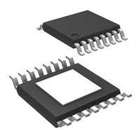
Package / Case
16-TSSOP Exposed Pad, 16-eTSSOP, 16-HTSSOP
Lead Free Status / RoHS Status
Lead free / RoHS Compliant
Voltage - Load
-
Lead Free Status / RoHS Status
Lead free / RoHS Compliant
Other names
620-1384-2
Available stocks
Company
Part Number
Manufacturer
Quantity
Price
Company:

Part Number:
A4954ELPTR-T
Manufacturer:
SILAN
Quantity:
24 000
Part Number:
A4954ELPTR-T
Manufacturer:
ALLEGRO/雅丽高
Quantity:
20 000


A4954
Sense Pins (LSSx)
In order to use PWM current control, a low-value resistor is
placed between the LSSx pin and ground for current sensing pur-
poses. To minimize ground-trace IR drops in sensing the output
current level, the current sensing resistor should have an indepen-
dent ground return to the star ground point. This trace should be
as short as possible. For low-value sense resistors, the IR drops in
the PCB can be significant, and should be taken into account.
When selecting a value for the sense resistor be sure not to
exceed the maximum voltage on the LSSx pin of ±500 mV at
maximum load. During overcurrent events, this rating may be
exceeded for short durations.
Ground
A star ground should be located as close to the A4954 as possible.
The copper ground plane directly under the exposed thermal pad
GND
GND
Bill of Materials
Item
1
2
3
C1
RS12, RS34
Reference
CAPACITANCE
BULK
C1
C2
C2
RS12
RS34
(for V
GND
REF
Application Information
GND
= 5 V, I
Value
0.25
0.22
100
OUT4
OUT3
OUT2
OUT1
VBB
OUT
= 2 A)
of the device makes a good location for the star ground point. The
exposed pad can be connected to ground for this purpose.
Layout
The PCB should have a thick ground plane. For optimum
electrical and thermal performance, the A4954 must be soldered
directly onto the board. On the underside of the A4954 package is
an exposed pad, which provides a path for enhanced thermal dis-
sipation. The thermal pad must be soldered directly to an exposed
surface on the PCB in order to achieve optimal thermal conduc-
tion. Thermal vias are used to transfer heat to other layers of the
PCB.
The load supply pin, VBB, should be decoupled with an electro-
lytic capacitor (typically 100 μF) in parallel with a lower valued
ceramic capacitor placed as close as practicable to the device.
Units
μF
μF
Ω
1
GND
GND
VREF34
IN3
IN4
IN2
IN1
VREF12
Dual Full-Bridge DMOS
X5R minimum, 50 V or greater
Electrolytic, 50 V or greater
2512, 1 W, 1% or better,
carbon film chip resistor
A4954
PWM Motor Driver
115 Northeast Cutoff
1.508.853.5000; www.allegromicro.com
Allegro MicroSystems, Inc.
Worcester, Massachusetts 01615-0036 U.S.A.
PAD
Description
LSS34
LSS12
OUT4
OUT3
OUT2
OUT1
VBB
VBB
R
R
C1
S34
S12
C2
V
BB
7
Related parts for A4954ELPTR-T
Image
Part Number
Description
Manufacturer
Datasheet
Request
R

Part Number:
Description:
Dual Full-bridge Dmos Pwm Motor Driver
Manufacturer:
Allegro MicroSystems, Inc.
Datasheet:

Part Number:
Description:
IC, HALL EFFECT SENSOR, Linear, SOIC-8
Manufacturer:
Allegro Microsystems Inc
Datasheet:
Part Number:
Description:
IC, HALL EFFECT SENSOR, Linear, SOIC-8
Manufacturer:
Allegro Microsystems Inc
Datasheet:
Part Number:
Description:
IC, HALL EFFECT SENSOR, Linear, SOIC-8
Manufacturer:
Allegro Microsystems Inc
Datasheet:

Part Number:
Description:
IC SWITCH INTERFACE 2CHAN 8-SOIC
Manufacturer:
Allegro Microsystems Inc
Datasheet:

Part Number:
Description:
IC SMOKE DETECTOR ION 16-DIP
Manufacturer:
Allegro Microsystems Inc
Datasheet:
Part Number:
Description:
IC SMOKE DETECTOR ION 16-DIP
Manufacturer:
Allegro Microsystems Inc
Datasheet:
Part Number:
Description:
IC SMOKE DETECTOR ION 16-DIP
Manufacturer:
Allegro Microsystems Inc
Datasheet:
Part Number:
Description:
IC SMOKE DETECTOR PHOTO 16-DIP
Manufacturer:
Allegro Microsystems Inc
Datasheet:
Part Number:
Description:
IC SMOKE DETECTOR ION 16-DIP
Manufacturer:
Allegro Microsystems Inc
Datasheet:
Part Number:
Description:
IC SMOKE DETECTOR PHOTO 16-DIP
Manufacturer:
Allegro Microsystems Inc
Datasheet:
Part Number:
Description:
IC SMOKE DETECTOR PHOTO 16-DIP
Manufacturer:
Allegro Microsystems Inc
Datasheet:
Part Number:
Description:
IC SMOKE DETECTOR ION 16-DIP
Manufacturer:
Allegro Microsystems Inc
Datasheet:
Part Number:
Description:
IC SMOKE DETECTOR PHOTO 16-SOIC
Manufacturer:
Allegro Microsystems Inc
Datasheet:

Part Number:
Description:
IC LED DRIVER HIGH BRIGHT 16-QFN
Manufacturer:
Allegro Microsystems Inc
Datasheet: