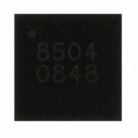
A8504EECTR-T Allegro Microsystems Inc, A8504EECTR-T Datasheet - Page 12

A8504EECTR-T
Manufacturer Part Number
A8504EECTR-T
Description
IC,Laser Diode/LED Driver,LLCC,28PIN,PLASTIC
Manufacturer
Allegro Microsystems Inc
Type
Backlight, White LED, RGBr
Datasheet
1.A8504EECTR-T.pdf
(18 pages)
Specifications of A8504EECTR-T
Topology
PWM, Step-Up (Boost)
Number Of Outputs
8
Internal Driver
Yes
Type - Primary
Backlight
Type - Secondary
RGB, White LED
Frequency
200kHz ~ 2MHz
Voltage - Supply
4.2 V ~ 5.5 V
Voltage - Output
47V
Mounting Type
Surface Mount
Package / Case
26-WFQFN Exposed Pad
Operating Temperature
-40°C ~ 85°C
Current - Output / Channel
45mA
Internal Switch(s)
Yes
Lead Free Status / RoHS Status
Lead free / RoHS Compliant
Efficiency
-
Lead Free Status / RoHS Status
Lead free / RoHS Compliant
Other names
620-1215-2
Available stocks
Company
Part Number
Manufacturer
Quantity
Price
Company:
Part Number:
A8504EECTR-T
Manufacturer:
HONGFA
Quantity:
20 000
A8504
7. Select output capacitor COUT (connect between the A8504
8. Select input capacitor CBAT (connect to battery input),
and the LEDs), given:
where I
output voltage ripple, 0.5% of V
Then:
Select a ceramic capacitor with a 35 or 50 V rating, X5R or
X7R grade. Usually capacitance at 35 V drops significantly
compared to the 0 V specification. Typically, this requires the
selection of a 2.2 μF capacitor to compensate for DC voltage
bias derating.
The rms current through capacitor should be selected such
that internally-generated temperature rise is limited to 10°C
to 20°C. The rms current through COUT is given by:
where r = ∆I
COUT should have an rms current rating greater than:
given:
where ∆V
sumed to be 1% of V
Select a 1 μF or higher, 25 or 35 V, ceramic capacitor, X5R or
X7R grade.
(40 mA × 6 )× {[0.74 + (0.36 / 12)]/(1–0.74)}
C
C
OUT
I
C
IN
OUT
COUTrms
BAT
INripple
= 0.554 mA/(8 × 2 MHz × 0.08) = 0.4 μF .
= (40 mA × 6) × 370 ns / 0.14 = 0.63 μF .
is the total output current, and ∆V
L
= ∆I
/ I
C
BAT
Figure 7. LED strings can be combined to allow various maximum current levels to be applied.
The “Connect” notes indicate LED strings connected together.
= I
OUT
is the input ripple voltage, which can be as-
L
I
LED
/ (V
OUT
100
100
200
= 0.554 mA /0.923 mA = 0.6.
25
25
25
25
25
25
25
25
50
50
50
50
(max)
= I
BAT
BAT
× [(D+r
OUT
. Then:
(min) × f
× t
of Strings
Quantity
on
2
8
7
6
5
4
3
2
1
4
3
2
1
2
1
1
OUT
/ 12) / (1 – D)]
WLED/RGB Backlight Driver for Medium Size LCDs
/ ∆V
SW
(0.05 × 27.7 = 0.14 V).
OUT
× ∆V
SEL1
H
H
H
H
H
H
H
H
H
H
H
L
L
L
L
,
INripple
1/2
SEL2
OUT
H
H
H
H
H
H
H
H
H
L
L
L
L
L
L
1/2
= 0.48 A.
is the
,
,
SEL3
H
H
H
H
H
H
H
H
L
L
L
L
L
L
L
(10)
(11)
(9)
LED1
Connect
Connect
Connect
Connect
9. Select the boost diode D1 (connect between the SW pins and
10. Select the compensation capacitor CC (connect between
High Output Current Operation
LED strings can be paralleled for higher current. The A8504
can sink up to 40 mA through each sink. These outputs can be
connected together with various possibilities for higher current
as shown in figure 7. As an example, for an application with up
to 50 mA using 3 parallel strings: LED1 connected with LED2,
LED3 with LED4, and LED5 with LED6; LED7 and LED8 open;
SEL1 and SEL3 set logic high, and SEL2 set low.
LED2
NC
Connect
Connect
The rms current through capacitor should be selected such
that internally-generated temperature rise is limited to 10°C.
The rms current through CBAT is given by:
the output). D1 should be a Schottky diode with low forward
drop and junction capacitance.
The diode reverse voltage rating should be greater than V
A 50 V diode rating is recommended.
The diode DC current rating should be greater than I
and the peak repetitive current rating should be greater than
I
the COMP pin and ground. Typically, use a 0.1 to 0.47 μF
capacitor for stability.
BAT
LED3
NC
NC
NC
+ ∆I
Connect
Connect
Connect
L
LED4
I
NC
NC
NC
NC
BATrms
/ 2.
Connect
LED5
NC
NC
NC
NC
NC
NC
NC
= (I
= [(40 mA × 6 )× 0.6] /
Connect
Connect
OUT
LED6
115 Northeast Cutoff
1.508.853.5000; www.allegromicro.com
Allegro MicroSystems, Inc.
Worcester, Massachusetts 01615-0036 U.S.A.
NC
NC
NC
NC
NC
NC
NC
NC
[(1 – 0.74) × 3.46] = 160 mA .
Connect
× r) / [(1 – D) × 3.46 ],
LED7
NC
NC
NC
NC
NC
NC
NC
NC
NC
NC
Connect
LED8
NC
NC
NC
NC
NC
NC
NC
NC
NC
NC
NC
OUT
(12)
OUT
12
.


