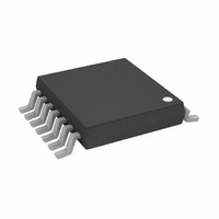
AD5252BRU10 Analog Devices Inc, AD5252BRU10 Datasheet - Page 2

AD5252BRU10
Manufacturer Part Number
AD5252BRU10
Description
IC,Digital Potentiometer,TSSOP,14PIN,PLASTIC
Manufacturer
Analog Devices Inc
Datasheet
1.AD5252BRUZ10.pdf
(28 pages)
Specifications of AD5252BRU10
Taps
256
Resistance (ohms)
10K
Number Of Circuits
2
Temperature Coefficient
650 ppm/°C Typical
Memory Type
Non-Volatile
Interface
I²C, 2-Wire Serial
Voltage - Supply
2.7 V ~ 5.5 V, ±2.25 V ~ 2.75 V
Operating Temperature
-40°C ~ 85°C
Mounting Type
Surface Mount
Package / Case
14-TSSOP
Resistance In Ohms
10K
Lead Free Status / RoHS Status
Contains lead / RoHS non-compliant
For Use With
AD5252EVAL - BOARD EVAL FOR AD5252
Lead Free Status / RoHS Status
Contains lead / RoHS non-compliant, Contains lead / RoHS non-compliant
Available stocks
Company
Part Number
Manufacturer
Quantity
Price
Part Number:
AD5252BRU100
Manufacturer:
ADI/亚德诺
Quantity:
20 000
AD5251/AD5252
TABLE OF CONTENTS
Features .............................................................................................. 1
Applications ....................................................................................... 1
General Description ......................................................................... 1
Functional Block Diagram .............................................................. 1
Revision History ............................................................................... 2
Electrical Characteristics ................................................................. 3
Absolute Maximum Ratings ............................................................ 8
Pin Configuration and Function Descriptions ............................. 9
Typical Performance Characteristics ........................................... 10
I
REVISION HISTORY
10/09—Rev. A to Rev. B
Changes to Figure 15 ...................................................................... 12
Changes to Figure 27 ...................................................................... 15
9/05—Rev. 0 to Rev. A
Updated Format .................................................................. Universal
Change to Figure 6 ......................................................................... 10
Changes to Figure 28 ...................................................................... 15
Changes to Figure 29 ...................................................................... 17
Changes to RDAC/EEMEM Quick Commands Section .......... 18
Changes to EEMEM Write Protection Section ........................... 18
Changes to Figure 37 ...................................................................... 22
Deleted Table 13 and Table 14 ...................................................... 23
Change to Figure 42 ....................................................................... 24
Change to Figure 46 ....................................................................... 25
Changes to Ordering Guide .......................................................... 27
6/04—Revision 0: Initial Version
2
C Interface ..................................................................................... 14
1 kΩ Version .................................................................................. 3
10 kΩ, 50 kΩ, 100 kΩ Versions .................................................. 5
Interface Timing Characteristics ................................................ 7
ESD Caution .................................................................................. 8
I
I
I
2
2
2
C Interface General Description ............................................ 14
C Interface Detail Description ............................................... 15
C-Compatible 2-Wire Serial Bus ........................................... 20
Rev. B | Page 2 of 28
Theory of Operation ...................................................................... 21
Applications Information .............................................................. 25
Outline Dimensions ....................................................................... 26
Linear Increment/Decrement Commands ............................. 21
±6 dB Adjustments (Doubling/Halving Wiper Setting) ....... 21
Digital Input/Output Configuration........................................ 22
Multiple Devices on One Bus ................................................... 22
Terminal Voltage Operation Range ......................................... 22
Power-Up and Power-Down Sequences .................................. 22
Layout and Power Supply Biasing ............................................ 23
Digital Potentiometer Operation ............................................. 23
Programmable Rheostat Operation ......................................... 23
Programmable Potentiometer Operation ............................... 24
LCD Panel V
Current-Sensing Amplifier ....................................................... 25
Adjustable High Power LED Driver ........................................ 25
Ordering Guide .......................................................................... 27
COM
Adjustment .................................................... 25


