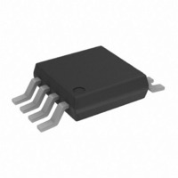
AD7418ARMZ Analog Devices Inc, AD7418ARMZ Datasheet - Page 15

AD7418ARMZ
Manufacturer Part Number
AD7418ARMZ
Description
1CH. I2C ADC W/ON-CHIP TEMP SENSOR I.C.
Manufacturer
Analog Devices Inc
Datasheet
1.AD7418ARZ.pdf
(24 pages)
Specifications of AD7418ARMZ
Function
Temp Monitoring System (Sensor)
Topology
ADC, Comparator, Register Bank
Sensor Type
Internal
Sensing Temperature
-40°C ~ 125°C
Output Type
I²C™
Output Alarm
No
Output Fan
Yes
Voltage - Supply
2.7 V ~ 5.5 V
Operating Temperature
-40°C ~ 125°C
Mounting Type
Surface Mount
Package / Case
8-TSSOP, 8-MSOP (0.118", 3.00mm Width)
Number Of Elements
1
Resolution
10Bit
Architecture
SAR
Input Polarity
Unipolar
Input Type
Voltage
Rated Input Volt
2.5V
Differential Input
No
Power Supply Requirement
Single
Single Supply Voltage (typ)
3.3/5V
Single Supply Voltage (min)
2.7V
Single Supply Voltage (max)
5.5V
Dual Supply Voltage (typ)
Not RequiredV
Dual Supply Voltage (min)
Not RequiredV
Dual Supply Voltage (max)
Not RequiredV
Power Dissipation
450mW
Differential Linearity Error
±1LSB
Integral Nonlinearity Error
±1LSB
Operating Temp Range
-40C to 125C
Operating Temperature Classification
Automotive
Mounting
Surface Mount
Pin Count
8
Package Type
MSOP
Input Signal Type
Single-Ended
Lead Free Status / RoHS Status
Lead free / RoHS Compliant
For Use With
EVAL-AD7416/7/8EBZ - BOARD EVALUATION FOR AD7416/7/8
Lead Free Status / Rohs Status
Compliant
Available stocks
Company
Part Number
Manufacturer
Quantity
Price
Company:
Part Number:
AD7418ARMZ
Manufacturer:
ST
Quantity:
6 219
Part Number:
AD7418ARMZ
Manufacturer:
ADI/亚德诺
Quantity:
20 000
Part Number:
AD7418ARMZ-REEL
Manufacturer:
ADI/亚德诺
Quantity:
20 000
Company:
Part Number:
AD7418ARMZ-REEL7
Manufacturer:
MAXIM
Quantity:
1 480
Part Number:
AD7418ARMZ-REEL7
Manufacturer:
ADI/亚德诺
Quantity:
20 000
•
written to the selected data register. This is illustrated in
Figure 16.
Writing two bytes of data to the T
setpoint register.
If 9-bit resolution is required for the temperature setpoints,
two bytes of data must be written to the T
SDA
1
1
SDA
SCL
START BY
SCL
START BY
(CONTINUED)
(CONTINUED)
AD741x = AD7416/AD7417/AD7418.
MASTER
AD741x = AD7416/AD7417/AD7418.
MASTER
1
SDA
SCL
START BY
AD741x = AD7416/AD7417/AD7418.
MASTER
SDA
SCL
1
1
1
1
Figure 17. Writing to the Address Pointer Register Followed by Two Bytes of Data to the T
1
1
D15
1
0
Figure 16. Writing to the Address Pointer Register Followed by a Single Byte of Data to the Selected Data Register
0
Figure 15. Writing to the Address Pointer Register to Select a Data Register for a Subsequent Read Operation
0
D14
SERIAL BUS ADDRESS BYTE
SERIAL BUS ADDRESS BYTE
0
0
SERIAL BUS ADDRESS BYTE
0
D13
MOST SIGNIFICANT DATA BYTE
1
FRAME 1
1
FRAME 1
1
D12
FRAME 1
OTI
A2
A2
FRAME 3
setpoint or T
A2
D11
SDA (CONTINUED)
A1
SCL (CONTINUED)
A1
OTI
A1
D10
setpoint and
A0
A0
HYST
A0
D9
R/W
R/W
AD741x
ACK. BY
R/W
D8
Rev. I | Page 15 of 24
AD741x
ACK. BY
9
ACK. BY
AD741x
ACK. BY
AD741x
9
1
D7
9
1
9
1
P7
1
1
1
P7
1
STOP BY
MASTER
D7
1
D6
P7
1
P6
P6
ADDRESS POINTER REGISTER BYTE
D6
T
address, the register address written to the address pointer
register, followed by two data bytes written to the selected
data register. This is illustrated in Figure 17.
P6
D5
P5
HYST
ADDRESS POINTER REGISTER BYTE
P5
D5
ADDRESS POINTER REGISTER BYTE
LEAST SIGNIFICANT DATA BYTE
setpoint registers. This consists of the serial bus
D4
P4
P5
P4
DATA BYTE
FRAME 2
FRAME 3
D4
P3
P4
D3
OTI
FRAME 2
FRAME 4
Setpoint or T
P3
FRAME 2
D3
P2
P3
D2
AD7416/AD7417/AD7418
P2
D2
P1
P2
D1
HYST
P1
D1
Setpoint Register
P0
P1
D0
P0
ACK. BY
AD741x
ACK. BY
AD741x
D0
9
P0
9
AD741x
ACK. BY
ACK. BY
AD741x
1
1
9
AD741x
9
ACK. BY
9
MASTER
1
1
STOP
BY
MASTER
MASTER
1
STOP
STOP
BY
BY


