AD9058AKD Analog Devices Inc, AD9058AKD Datasheet - Page 7
AD9058AKD
Manufacturer Part Number
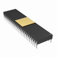
AD9058AKD
Description
IC,A/D CONVERTER,DUAL,8-BIT,DIP,48PIN
Manufacturer
Analog Devices Inc
Datasheet
1.AD9058AJJ.pdf
(12 pages)
Specifications of AD9058AKD
Rohs Status
RoHS non-compliant
Number Of Bits
8
Sampling Rate (per Second)
50M
Data Interface
Parallel
Number Of Converters
2
Power Dissipation (max)
960mW
Voltage Supply Source
Analog and Digital, Dual ±
Operating Temperature
0°C ~ 70°C
Mounting Type
Through Hole
Package / Case
48-CDIP (0.600", 15.24mm)
Lead Free Status / RoHS Status
Available stocks
Company
Part Number
Manufacturer
Quantity
Price


REV. D
The on-board voltage reference, +V
that has sufficient drive capability for both reference ladders.
It provides a 2 V reference that can drive both ADCs in the
AD9058 for unipolar positive operation (0 V to 2 V).
USING THE AD9058
Refer to Figure 2. Using the internal voltage reference con-
nected to both ADCs as shown reduces the number of external
components required to create a complete data acquisition
system. The input ranges of the ADCs are positive unipolar
in this configuration, ranging from 0 V to 2 V. Bipolar input
signals are buffered, amplified, and offset into the proper input
range of the ADC using a good low distortion amplifier such
as the AD9617 or AD9618.
The AD9058 offers considerable flexibility in selecting the analog
input ranges of the ADCs; the two independent ADCs can even
have different input ranges if required. In Figure 3, the AD9058
is shown configured for ± 1 V operation.
The “Reference Ladder Offset” shown in the specifications table
refers to the error between the voltage applied to the +V
or –V
at the analog input to achieve a 1111 1111 or 0000 0000 transi-
tion. This indicates the amount of adjustment range that must be
designed into the reference circuit for the AD9058.
The diode shown between ground and –V
biased and is used to prevent latch-up. Its use is recommended
for applications in which power supply sequencing might allow
+V
S
to be applied before –V
REF
(bottom) of the reference ladder and the voltage required
ANALOG
ANALOG
0.125V
0.125V
IN A
IN B
20k
10k
50
AD708
50
AD580
1/2
+5V
1
2
0.1 F
S
; or the +V
10k
3
AD9618
AD9618
20k
400
150
400
INT
AD708
Figure 3. AD9058 Using External Voltage References
1/2
, is a band gap reference
S
supply is not current
–5V
S
2N3906
is normally reverse-
10k
150
0.1 F
5k
5
0.1 F
+5V
2N3904
0.1 F
10
REF
–1V
ENCODE
(top)
1V
1V
43
38
40
3
6
8
1
+V
A
–V
–V
COMP
AD9058
(J-LEAD)
+V
A
–7–
IN A
IN B
ENCODE
REF B
REF A
REF B
limited. If the negative supply is allowed to float (the +5 V supply
is powered up before the –5 V supply), substantial +5 V supply
current will attempt to flow through the substrate (V
tact) to ground. If this current is not limited to <500 mA, the part
may be destroyed. The diode prevents this potentially destructive
condition from occurring.
Timing
Refer to the AD9058 Timing Diagram, Figure 4. The AD9058
provides latched data outputs with no pipeline delay. To conserve
power, the data outputs have relatively slow rise and fall times.
When designing system timing, it is important to observe (1) setup
and hold times; and (2) the intervals when data is changing.
Figure 3 shows 2 kΩ pull-down resistors on each of the D
output data bits. When operating at conversion rates higher than
40 MSPS, these resistors help equalize rise and fall times and
ease latching the output data into external latches. The 74ACT
logic family devices have short setup and hold times and are the
recommended choices for speeds of 40 MSPS or more.
Layout
To ensure optimum performance, a single low impedance ground
plane is recommended. Analog and digital grounds should be con-
nected together and to the ground plane at the AD9058 device.
Analog and digital power supplies should be bypassed to ground
through 0.1 µF ceramic capacitors as close to the unit as possible.
For prototyping or evaluation, surface-mount sockets are available
from Methode Electronics, Inc. (Part No. 213-0320602) for
evaluating AD9058 surface-mount packages. To evaluate the
REF A
10
A
4, 19, 21,
25, 27, 42
ENCODE
36
D
D
D
D
7A
7B
B
0A
0B
(MSB)
(MSB)
(LSB)
(LSB)
+V
–V
S
S
50k
18
17
16
15
14
13
12
11
5, 9, 22,
24, 37, 41
28
29
30
31
32
33
34
35
7, 20,
26, 39
0.1 F
74ACT04
0.1 F
1N4001
+5V
RZ1
RZ2
1k
–5V
(SEE TEXT)
10pF
AD9058
CLOCK
CLOCK
8
8
S
supply con-
0
–D
7
Related parts for AD9058AKD
Image
Part Number
Description
Manufacturer
Datasheet
Request
R

Part Number:
Description:
±1.7g Dual-Axis IMEMS Accelerometer Evaluation Board
Manufacturer:
Analog Devices Inc
Datasheet:

Part Number:
Description:
Inertial Sensor Evaluation System
Manufacturer:
Analog Devices Inc
Datasheet:
Part Number:
Description:
Manufacturer:
Analog Devices Inc
Datasheet:
Part Number:
Description:
Manufacturer:
Analog Devices Inc
Datasheet:
Part Number:
Description:
Manufacturer:
Analog Devices Inc
Datasheet:
Part Number:
Description:
Manufacturer:
Analog Devices Inc
Datasheet:
Part Number:
Description:
Manufacturer:
Analog Devices Inc
Datasheet:
Part Number:
Description:
Manufacturer:
Analog Devices Inc
Datasheet:
Part Number:
Description:
Manufacturer:
Analog Devices Inc
Datasheet:
Part Number:
Description:
Manufacturer:
Analog Devices Inc
Datasheet:
Part Number:
Description:
Manufacturer:
Analog Devices Inc
Datasheet:
Part Number:
Description:
Manufacturer:
Analog Devices Inc
Datasheet:
Part Number:
Description:
Manufacturer:
Analog Devices Inc
Datasheet: