AD96687BQ Analog Devices Inc, AD96687BQ Datasheet - Page 5
AD96687BQ
Manufacturer Part Number
AD96687BQ
Description
Voltage Comparator IC
Manufacturer
Analog Devices Inc
Type
with Latchr
Datasheet
1.AD96687BRZ.pdf
(8 pages)
Specifications of AD96687BQ
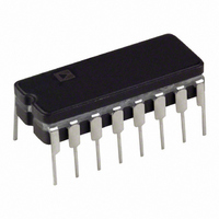
Package / Case
16-DIP
Number Of Elements
2
Output Type
Complementary, ECL, Open-Emitter
Mounting Type
Through Hole
Lead Free Status / RoHS Status
Contains lead / RoHS non-compliant
Available stocks
Company
Part Number
Manufacturer
Quantity
Price

Part Number:
AD96687BQ
Manufacturer:
ADI/亚德诺
Quantity:
20 000


APPLICATIONS INFORMATION
The AD96685/AD96687 comparators are very high speed devices.
Consequently, high speed design techniques must be employed
to achieve the best performance. The most critical aspect of any
AD96685/AD96687 design is the use of a low impedance
ground plane.
Another area of particular importance is power supply decoupling.
Normally, both power supply connections should be separately
decoupled to ground through 0.1 µF ceramic and 0.001 µF mica
capacitors. The basic design of comparator circuits makes the
negative supply somewhat more sensitive to variations. As a
result, more attention should be placed on ensuring a “clean”
negative supply.
The LATCH ENABLE input is active LOW (latched). If the
latching function is not used, the LATCH ENABLE input should
be grounded (ground is an ECL logic HIGH). The LATCH
ENABLE input of the AD96687 should be tied to –2.0 V or left
“floating,” to disable the latching function. An alternate use of
the LATCH ENABLE input is as a hysteresis control input. By
varying the voltage at the LATCH ENABLE input for the
AD96685 and the differential voltage between both latch
inputs for the AD96687, small variations in the hysteresis can
be achieved.
Typical Performance Characteristics–AD96685/AD96687
Occasionally, one of the two comparator stages within the
AD96687 will not be used. The inputs of the unused comparator
should not be allowed to “float.” The high internal gain may
cause the output to oscillate (possibly affecting the other com-
parator which is being used) unless the output is forced into a
fixed state. This is easily accomplished by ensuring that the two
inputs are at least one diode drop apart, while also grounding
the LATCH ENABLE input.
The best performance will be achieved with the use of proper
ECL terminations. The open-emitter outputs of the AD96685/
AD96687 are designed to be terminated through 50 Ω resis-
tors to –2.0 V, or any other equivalent ECL termination. If high
speed ECL signals must be routed more than a few centimeters,
MicroStrip or StripLine techniques may be required to ensure
proper transition times and prevent output ringing.
The AD96685/AD96687 have been specifically designed to
reduce propagation delay dispersion over an input overdrive
range of 100 mV to 1 V. Propagation delay dispersion is the
change in propagation delay which results from a change in
the degree of overdrive (how far the switching point is exceeded
by the input). The overall result is a higher degree of timing
accuracy since the AD96685/AD96687 are far less sensitive
to input variations than most comparator designs.
Related parts for AD96687BQ
Image
Part Number
Description
Manufacturer
Datasheet
Request
R

Part Number:
Description:
±1.7g Dual-Axis IMEMS Accelerometer Evaluation Board
Manufacturer:
Analog Devices Inc
Datasheet:

Part Number:
Description:
Inertial Sensor Evaluation System
Manufacturer:
Analog Devices Inc
Datasheet:
Part Number:
Description:
Manufacturer:
Analog Devices Inc
Datasheet:
Part Number:
Description:
Manufacturer:
Analog Devices Inc
Datasheet:
Part Number:
Description:
Manufacturer:
Analog Devices Inc
Datasheet:
Part Number:
Description:
Manufacturer:
Analog Devices Inc
Datasheet:
Part Number:
Description:
Manufacturer:
Analog Devices Inc
Datasheet:
Part Number:
Description:
Manufacturer:
Analog Devices Inc
Datasheet:
Part Number:
Description:
Manufacturer:
Analog Devices Inc
Datasheet:
Part Number:
Description:
Manufacturer:
Analog Devices Inc
Datasheet:
Part Number:
Description:
Manufacturer:
Analog Devices Inc
Datasheet:
Part Number:
Description:
Manufacturer:
Analog Devices Inc
Datasheet:
Part Number:
Description:
Manufacturer:
Analog Devices Inc
Datasheet: