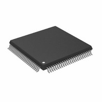
AD9882KSTZ-140 Analog Devices Inc, AD9882KSTZ-140 Datasheet - Page 35

AD9882KSTZ-140
Manufacturer Part Number
AD9882KSTZ-140
Description
IC,TV/VIDEO CIRCUIT,Video Digitizer,CMOS,QFP,100PIN,PLASTIC
Manufacturer
Analog Devices Inc
Datasheet
1.AD9882KSTZ-100.pdf
(40 pages)
Specifications of AD9882KSTZ-140
Applications
Video
Interface
Analog, DVI
Voltage - Supply
3.15 V ~ 3.45 V
Package / Case
100-LQFP
Mounting Type
Surface Mount
Lead Free Status / RoHS Status
Lead free / RoHS Compliant
Available stocks
Company
Part Number
Manufacturer
Quantity
Price
Company:
Part Number:
AD9882KSTZ-140
Manufacturer:
ADI
Quantity:
717
Company:
Part Number:
AD9882KSTZ-140
Manufacturer:
Analog Devices Inc
Quantity:
10 000
SYNC PROCESSING ENGINE
SYNC SLICER
This section describes the basic operation of the sync
processing engine (see Figure 20).
The purpose of the sync slicer is to extract the sync signal from
the green graphics channel. A sync signal is not present on all
graphics systems (only those with sync-on-green). The sync
signal is extracted from the green channel in a two-step process.
1.
2.
SYNC SEPARATOR
A sync separator extracts the Vsync signal from a composite
sync signal. It does this through a low-pass filter-like or
integrator-like operation. It works on the idea that the Vsync
signal stays active for a much longer time than the Hsync signal.
So, it rejects any signal shorter than a threshold value, which is
somewhere between an Hsync pulse width and a Vsync pulse
width.
SOG input is clamped to its negative peak (typically 0.3 V
below the black level).
The signal goes to a comparator with a variable trigger
level, nominally 0.15 V above the clamped level. The
output signal is typically a composite sync signal
containing both Hsync and Vsync.
HSYNC IN
VSYNC IN
SOG
ACTIVITY
DETECT
SYNC STRIPPER
ACTIVITY
DETECT
NEGATIVE
CLAMP
PEAK
PLL
MUX 3
Figure 20. Sync Processing Block Diagram
COMP
SYNC
MUX 2
ACTIVITY
DETECT
HSYNC
COAST
Rev. 0 | Page 35 of 40
POLARITY
POLARITY
DETECT
DETECT
MUX 1
GENERATOR
CLOCK
The sync separator on the AD9882A is an 8-bit digital counter
with a 5 MHz clock. It works independently of the polarity of
the composite sync signal. Polarities are determined elsewhere
on the chip. The counter counts up when Hsync pulses are
present. But since Hsync pulses are relatively short in width, the
counter reaches only a value of N before the pulse ends. It then
starts counting down, eventually reaching 0 before the next
Hsync pulse arrives. The specific value of N varies for different
video modes, but is always less than 255. For example, with a
1 ms width Hsync, the counter only reaches 5 (1 µs/200 ns = 5).
When Vsync is present on the composite sync, the counter also
counts up. However, because the Vsync signal is much longer, it
counts to a higher number, M. For most video modes, M is at
least 255. So, Vsync can be detected on the composite sync
signal by detecting when the counter counts to higher than N.
The specific count that triggers detection (t) can be program-
med through the serial register (0x0E).
Once Vsync has been detected, a similar process detects when it
goes inactive. At detection, the counter first resets to 0, then
starts counting up when Vsync goes away. In a way similar to
the previous case, it detects the absence of Vsync when the
counter reaches the threshold count (T). In this way, it rejects
noise and/or serration pulses. Once Vsync is determined to be
absent, the counter resets to 0 and begins the cycle again.
SYNC SEPARATOR
DVI
INTEGRATOR
HSYNC OUT
PIXEL CLOCK
1/S
HSYNC
VSYNC
DE
VSYNC
AD9882A
MUX 4
MUX 5
MUX 6
SOG OUT
HSYNC OUT
VSYNC OUT
DE
AD9882A


