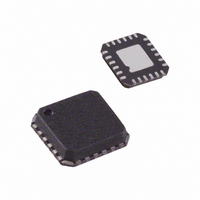
ADN8810ACPZ-REEL7 Analog Devices Inc, ADN8810ACPZ-REEL7 Datasheet - Page 14

ADN8810ACPZ-REEL7
Manufacturer Part Number
ADN8810ACPZ-REEL7
Description
Tunable Laser Controller
Manufacturer
Analog Devices Inc
Datasheet
1.ADN8810ACPZ-REEL7.pdf
(16 pages)
Specifications of ADN8810ACPZ-REEL7
Function
Current Source (12 Bit)
Current - Output
300mA
Operating Temperature
-40°C ~ 85°C
Mounting Type
Surface Mount
Package / Case
24-LFCSP
Lead Free Status / RoHS Status
Lead free / RoHS Compliant
Voltage - Input
-
Accuracy
-
Sensing Method
-
Lead Free Status / RoHS Status
Lead free / RoHS Compliant
ADN8810
LOGIC GROUND
To improve thermal dissipation, the slug on the bottom of the
LFCSP package should be soldered to the PC board with
multiple vias into a low noise ground plane. Connecting these
vias to a copper area on the bottom side of the board will
further improve thermal dissipation.
Use identical trace lengths for the two output sense resistors.
These lengths are shown as X and Y in Figure 24. Differences in
trace lengths cause differences in parasitic series resistance.
Because the sense resistors can be as low as 1.37 Ω, small
parasitic differences can lower both the output current accuracy
and the output impedance. Application Note AN-619 shows a
good layout for these traces.
DIGITAL LOGIC
TO OTHER 5V
RETURN
Figure 24. Use Identical Trace Lengths for Sense Resistors
Figure 23. Star Supply and Ground Technique
ADN8810
DVDD
5V
IOUT
R
AVDD
FB
SN
POWER SUPPLY
ADN8810
R
SN
PVDD
3V
R
Y
DGND
DVSS
SN
GND
AVSS
IOUT
X
TO LOAD
LOAD
LOAD
GND
Rev. A | Page 14 of 16
SUGGESTED PAD LAYOUT FOR CP-24 PACKAGE
Figure 25 shows the dimensions for the PC board pad layout for
the ADN8810. The package is a 4 mm × 4 mm, 24-lead LFCSP.
The metallic slug underneath the package should be soldered to
a copper pad connected to AVSS, the lowest supply voltage to
the ADN8810. For single-supply applications, this is ground.
Use multiple vias to this pad to improve the thermal dissipation
of the package.
(4.36)
0.172
DIMENSIONS ARE SHOWN
IN INCHES AND (MM).
0.004
(0.10)
Figure 25. Suggested PC Board Layout for CP-24 Pad Landing
0.109
(2.78)
CONTROLLING DIMENSIONS ARE IN MILLIMETERS
(2.1) SQ
0.827
0.027
(0.69)
PACKAGE
OUTLINE
(0.28)
(0.50)
0.011
0.020


