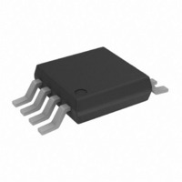
ADT75BRMZ-REEL7 Analog Devices Inc, ADT75BRMZ-REEL7 Datasheet - Page 11

ADT75BRMZ-REEL7
Manufacturer Part Number
ADT75BRMZ-REEL7
Description
IC,TEMPERATURE SENSOR,TSSOP,8PIN,PLASTIC
Manufacturer
Analog Devices Inc
Datasheet
1.ADT75ARMZ.pdf
(24 pages)
Specifications of ADT75BRMZ-REEL7
Function
Temp Monitoring System (Sensor)
Topology
ADC (Sigma Delta), Comparator, Register Bank
Sensor Type
Internal
Sensing Temperature
-55°C ~ 125°C
Output Type
I²C™/SMBus™
Output Alarm
No
Output Fan
No
Voltage - Supply
3 V ~ 5.5 V
Operating Temperature
-55°C ~ 125°C
Mounting Type
Surface Mount
Package / Case
8-TSSOP, 8-MSOP (0.118", 3.00mm Width)
Lead Free Status / RoHS Status
Lead free / RoHS Compliant
Available stocks
Company
Part Number
Manufacturer
Quantity
Price
Company:
Part Number:
ADT75BRMZ-REEL7
Manufacturer:
MAXIM
Quantity:
359
Part Number:
ADT75BRMZ-REEL7
Manufacturer:
ADI原装
Quantity:
20 000
Configuration register functions consist of
TEMPERATURE DATA FORMAT
One LSB of the ADC corresponds to 0.0625°C. The ADC can
theoretically measure a temperature range of 255°C (−128°C to
+127°C ), but the ADT75 is guaranteed to measure a low value
temperature limit of −55°C to a high value temperature limit of
+125°C. The temperature measurement result is stored in the
16-bit temperature value register and is compared with the high
temperature limit stored in the T
hysteresis limit in the T
Temperature data in the temperature value register, the T
setpoint register and the T
by a 12-bit twos complement word. The MSB is the temperature
sign bit. The four LSBs, Bit DB0 to Bit DB3, are not part of the
temperature conversion result and are always 0s. Table 6 shows
the temperature data format without Bit DB0 to Bit DB3.
Reading back the temperature from the temperature value
register requires a 2-byte read unless only a 1°C (8-bit)
resolution is required, then a 1-byte read is required. Designers
that use a 9-bit temperature data format can still use the ADT75
by ignoring the last three LSBs of the 12-bit temperature value.
These three LSBs are Bit D4 to Bit D6 in Table 6.
Switching between normal operation and full power-down.
Switching between comparator and interrupt event modes.
Setting the OS/ALERT pin active polarity.
Setting the number of faults that activate the
OS/ALERT pin.
Enabling the one-shot mode.
Enabling the SMBus alert function mode on the
OS/ALERT pin.
HYST
HYST
setpoint register.
setpoint register, is represented
OS
setpoint register and the
OS
Rev. A | Page 11 of 24
Table 6. 12-Bit Temperature Data Format
Temperature
−55°C
−50°C
−25°C
−0.0625°C
0°C
+0.0625°C
+10°C
+25°C
+50°C
+75°C
+100°C
+125°C
Temperature Conversion Formulas
12-Bit Temperature Data Format
9-Bit Temperature Data Format
8-Bit Temperature Data Format
1
2
3
4
5
6
For ADC code, use all 12 bits of the data byte, including the sign bit.
For ADC code, Bit DB11 (sign bit) is removed from the ADC code.
For ADC code, use all 9 bits of the data byte, including the sign bit.
Bit DB8 (sign bit) is removed from the ADC code.
For the ADC code, use all 8 bits of the data byte, including the sign bit.
Bit DB7 (sign bit) is removed from the ADC code.
Positive Temperature = ADC Code(d)/16
Negative Temperature = (ADC Code(d)
Negative Temperature = (ADC Code(d)
Positive Temperature = ADC Code(d)/2
Negative Temperature = (ADC Code(d)
Negative Temperature = (ADC Code(d)
Positive Temperature = ADC Code(d)
Negative Temperature = ADC Code(d)
Negative Temperature = ADC Code(d)
Bit DB7 (sign bit) is removed from the ADC code.
Digital Output (Binary)
DB15 to DB4
1100 1001 0000
1100 1110 0000
1110 0111 0000
1111 1111 1111
0000 0000 0000
0000 0000 0001
0000 1010 0000
0001 1001 0000
0011 0010 0000
0100 1011 0000
0110 0100 0000
0111 1101 0000
Digital Output (Hex)
0xC90
0xCE0
0xE70
0xFFF
0x000
0x001
0x0A0
0x190
0x320
0x4B0
0x640
0x7D0
1
2
3
4
5
6
− 4096)/16, or
– 2048)/16
– 512)/2, or
– 256)/2
– 256, or
– 128
ADT75


