ATS643LSHTN-I1-T Allegro Microsystems Inc, ATS643LSHTN-I1-T Datasheet
ATS643LSHTN-I1-T
Specifications of ATS643LSHTN-I1-T
Available stocks


Related parts for ATS643LSHTN-I1-T


ATS643LSHTN-I1-T Summary of contents
Page 1
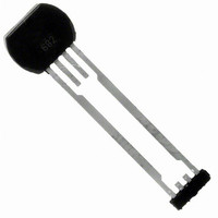
Gear Tooth Sensor IC with Continuous Update Features and Benefits ▪ Fully-optimized differential digital gear tooth sensor IC ▪ Single chip-IC for high reliability ▪ Internal current regulator for 2-wire operation ▪ Small mechanical size (8 mm diameter x 5.5 ...
Page 2
... True zero-speed operation ▪ Undervoltage lockout ▪ Wide operating voltage range ▪ Defined power-on state Part Number ATS643LSHTN-I1-T Tape and Reel 13-in. 800 pcs./reel ATS643LSHTN-I2-T Tape and Reel 13-in. 800 pcs./reel * Contact Allegro for additional packing options. Some restrictions may apply to certain types of sales. Contact Allegro for details ...
Page 3
ATS643LSH OPERATING CHARACTERISTICS using reference target 60-0, T Characteristic Symbol ELECTRICAL CHARACTERISTICS Supply Voltage V CC Undervoltage Lockout V CC(UV) Supply Zener Clamp Voltage V I CC(Low) Supply Current I CC(High) I Supply Current Ratio CC(High) I CC(Low) POWER-ON CHARACTERISTICS ...
Page 4
ATS643LSH OPERATING CHARACTERISTICS (continued) using reference target 60-0, T Characteristic Symbol SWITCHPOINT CHARACTERISTICS Rotation Speed Bandwidth Operate Point Release Point 3 CALIBRATION Initial Calibration Period AGC Calibration Disable Start Mode Hysteresis PO DAC CHARACTERISTICS Dynamic Offset Cancellation Tracking Data Resolution ...
Page 5
ATS643LSH REFERENCE TARGET, 60-0 (60 Tooth Target) Characteristics Symbol Outside Diameter D o Face Width F Circular Tooth Length t Circular Valley Length t v Tooth Whole Depth h t Material Reference Gear Magnetic Gradient Amplitude with Reference to Air ...
Page 6
ATS643LSH Duty Cycle at 1000 – (° Continued on the next page. Self-Calibrating, Zero-Speed Differential Gear Tooth Sensor IC with Continuous Update Characteristic Data Data taken ...
Page 7
ATS643LSH I CC (Low – (° CC(High – (°C) A Output current in relation to sensed mag- netic ...
Page 8
ATS643LSH THERMAL CHARACTERISTICS may require derating at maximum conditions, see application information Characteristic Package Thermal Resistance Self-Calibrating, Zero-Speed Differential Gear Tooth Sensor IC with Continuous Update Symbol Test Conditions Minimum-K PCB (single-sided with copper limited to solder pads) R θJA ...
Page 9
ATS643LSH Hall Technology. The ATS643 contains a single-chip differ- ential Hall effect sensor IC, a samarium cobalt pellet, and a flat ferrous pole piece (concentrator). As shown in figure 1, the Hall IC supports two Hall elements, which sense the ...
Page 10
ATS643LSH induced by the target and sensed by the Hall elements. When V transitions through a switchpoint from the appropriate PROC higher or lower level, it triggers IC switch turn-on and turn-off. As shown in figure 3, when the switch ...
Page 11
ATS643LSH Power-On State Operation. The ATS643 is guaranteed to power-on in the high current state, I CC(High) Initial Edge Detection. The device self-calibrates using the initial teeth sensed, and then enters Running mode. This results in reduced accuracy for a ...
Page 12
ATS643LSH Start Mode Hysteresis. This feature helps to ensure optimal self-calibration by rejecting electrical noise and low-amplitude target vibration during initialization. This prevents AGC from calibrating the IC on such spurious signals. Calibration can be performed using the actual target ...
Page 13
ATS643LSH Undervoltage Lockout. When the supply voltage falls below the minimum operating voltage, V and remains high regardless of the state of the magnetic gradi- ent from the target. This lockout feature prevents false signals, caused by undervoltage conditions, from ...
Page 14
ATS643LSH The device must be operated below the maximum junction temperature of the device Under certain combinations of J(max) peak conditions, reliable operation may require derating sup- plied power or improving the heat dissipation properties of the application. ...
Page 15
ATS643LSH 1.10 F 8.00±0.05 5.80±0.05 E1 1.70±0.10 4.00±0.10 5.00±0. 24.65±0.10 13.10±0.10 A 5.50±0.10 Copyright ©2004-2009, Allegro MicroSystems, Inc. The products described herein are manufactured under one or more of the following U.S. patents: 5,264,783; 5,389,889; 5,442,283; 5,517,112; 5,581,179; ...