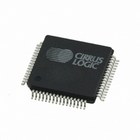
CS42448-DQZR Cirrus Logic Inc, CS42448-DQZR Datasheet - Page 5

CS42448-DQZR
Manufacturer Part Number
CS42448-DQZR
Description
IC,Soundcard Circuits,CMOS,QFP,64PIN,PLASTIC
Manufacturer
Cirrus Logic Inc
Type
Audio Codecr
Datasheet
1.CS42448-CQZ.pdf
(64 pages)
Specifications of CS42448-DQZR
Data Interface
Serial
Resolution (bits)
24 b
Number Of Adcs / Dacs
6 / 8
Sigma Delta
Yes
Dynamic Range, Adcs / Dacs (db) Typ
105 / 108 (Differential), 102 / 105 (Single-Ended)
Voltage - Supply, Analog
3.14 V ~ 5.25 V
Voltage - Supply, Digital
3.14 V ~ 5.25 V
Operating Temperature
-40°C ~ 105°C
Mounting Type
Surface Mount
Package / Case
64-LQFP
Lead Free Status / RoHS Status
Lead free / RoHS Compliant
For Use With
598-1151 - BOARD EVAL FOR CS42448 CODEC
Lead Free Status / RoHS Status
Lead free / RoHS Compliant
Available stocks
Company
Part Number
Manufacturer
Quantity
Price
Company:
Part Number:
CS42448-DQZR
Manufacturer:
CIRRUS
Quantity:
32 000
Company:
Part Number:
CS42448-DQZR
Manufacturer:
Cirrus Logic Inc
Quantity:
10 000
CS42448
Figure 37.DSM Transition Band ................................................................................................................ 57
Figure 38.DSM Transition Band (Detail) ................................................................................................... 58
Figure 39.DSM Passband Ripple .............................................................................................................. 58
Figure 40.QSM Stopband Rejection ......................................................................................................... 58
Figure 41.QSM Transition Band ................................................................................................................ 58
Figure 42.QSM Transition Band (Detail) ................................................................................................... 58
Figure 43.QSM Passband Ripple .............................................................................................................. 58
Figure 44.SSM Stopband Rejection .......................................................................................................... 59
Figure 45.SSM Transition Band ................................................................................................................ 59
Figure 46.SSM Transition Band (detail) .................................................................................................... 59
Figure 47.SSM Passband Ripple .............................................................................................................. 59
Figure 48.DSM Stopband Rejection .......................................................................................................... 59
Figure 49.DSM Transition Band ................................................................................................................ 59
Figure 50.DSM Transition Band (detail) .................................................................................................... 60
Figure 51.DSM Passband Ripple .............................................................................................................. 60
Figure 52.QSM Stopband Rejection ......................................................................................................... 60
Figure 53.QSM Transition Band ................................................................................................................ 60
Figure 54.QSM Transition Band (detail) .................................................................................................... 60
Figure 55.QSM Passband Ripple .............................................................................................................. 60
LIST OF TABLES
Table 1. I/O Power Rails ............................................................................................................................. 8
Table 2. Single-Speed Mode Common Frequencies ................................................................................ 30
Table 3. Double-Speed Mode Common Frequencies ............................................................................... 30
Table 4. Quad-Speed Mode Common Frequencies ................................................................................. 30
Table 5. I²S, LJ, RJ Clock Ratios .............................................................................................................. 31
Table 6. OLM#1 Clock Ratios ................................................................................................................... 31
Table 7. OLM#2 Clock Ratios ................................................................................................................... 31
Table 8. TDM Clock Ratios ....................................................................................................................... 31
Table 9. Serial Audio Interface Channel Allocations ................................................................................. 34
Table 10. MCLK Frequency Settings for I²S, Left and Right Justified Interface Formats .......................... 43
Table 12. DAC Digital Interface Formats .................................................................................................. 44
Table 11. MCLK Frequency Settings for TDM & OLM Interface Formats ................................................. 44
Table 13. ADC Digital Interface Formats .................................................................................................. 45
Table 14. Example AOUT Volume Settings .............................................................................................. 49
Table 15. Example AIN Volume Settings .................................................................................................. 50
DS648F3
5


