CY7B933-400JXC Cypress Semiconductor Corp, CY7B933-400JXC Datasheet - Page 9
CY7B933-400JXC
Manufacturer Part Number
CY7B933-400JXC
Description
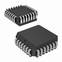
IC,Fiber-Optic Receiver,BICMOS,LDCC,28PIN,PLASTIC
Manufacturer
Cypress Semiconductor Corp
Series
HOTlink™r
Type
Transmitter and Receiverr
Datasheet
1.CY7B923-JXC.pdf
(40 pages)
Specifications of CY7B933-400JXC
Protocol
Fibre Channel
Voltage - Supply
4.5V ~ 5.5V
Mounting Type
Surface Mount
Package / Case
28-PLCC
Lead Free Status / RoHS Status
Lead free / RoHS Compliant
Number Of Drivers/receivers
-
Lead Free Status / RoHS Status
Lead free / RoHS Compliant
Other names
428-2906-5
CY7B933-400JXC
CY7B933-400JXC
Available stocks
Company
Part Number
Manufacturer
Quantity
Price
Company:

Part Number:
CY7B933-400JXC
Manufacturer:
Cypress Semiconductor Corp
Quantity:
10 000
Company:
Part Number:
CY7B933-400JXCT
Manufacturer:
Cypress Semiconductor Corp
Quantity:
10 000


The read pulse (RP) is derived from the feedback counter used
in the PLL multiplier. It is a byte-rate pulse stream with the proper
phase and pulse widths to allow transfer of data from an
asynchronous FIFO. Pulse width is independent of CKW duty
cycle, since proper phase and duty cycle is maintained by the
PLL. The RP pulse stream ensures correct data transfers
between asynchronous FIFOs and the transmitter input latch
with no external logic.
Test Logic
Test logic includes the initialization and control for the BIST
generator, the multiplexer for test mode clock distribution, and
control logic to properly select the data encoding. Test logic is
discussed in detail in
Mode Description on page
CY7B933 HOTLink Receiver Block Diagram
Description
Serial Data Inputs
Two pairs of differential line receivers are the inputs for the serial
data stream. INA± or INB± can be selected with the A/B input.
INA± is selected with A/B HIGH and INB± is selected with A/B
LOW. The threshold of A/B is compatible with the ECL 100K
signals from PECL fiber optic interface modules. TTL logic
elements can be used to select the A or B inputs by adding a
resistor pull-up to the TTL driver connected to A/B. The
differential threshold of INA± and INB± will accommodate wire
interconnect with filtering losses or transmission line attenuation
greater than 20 db (V
to fiber optic interface modules (any ECL logic family, not limited
to ECL 100K). The common mode tolerance will accommodate
a wide range of signal termination voltages. The highest HIGH
input that can be tolerated is V
input that can be interpreted correctly is V
PECL-TTL Translator
The function of the INB(INB+) input and the SI(INB–) input is
defined by the connections on the SO output pin. If the
PECL/TTL translator function is not required, the SO output is
wired to VCC. A sensor circuit detects this connection and
causes the inputs to become INB± (a differential line-receiver
serial-data input). If the PECL/TTL translator function is required,
the SO output is connected to its normal TTL load (typically one
or more TTL inputs, but no pull-up resistor) and the INB+ input
becomes single-ended ECL 100K, serial data input (INB) and the
INB– input becomes single-ended, ECL 100K status input (SI).
This positive-referenced PECL-to-TTL translator is provided to
eliminate external logic between an PECL fiber-optic interface
module “carrier detect” output and the TTL input in the control
logic. The input threshold is compatible with ECL 100K levels
(+5-V referenced). It can also be used as part of the link status
indication logic for wire connected systems.
Clock Synchronization
The clock synchronization function is performed by an
embedded PLL that tracks the frequency of the incoming bit
stream and aligns the phase of its internal bit rate clock to the
Document #: 38-02017 Rev. *H
CY7B923 HOTLink Transmitter Operating
DIF
> 50 mv) or can be directly connected
11.
IN
= V
CC
, and the lowest LOW
IN
= GND+2.0V.
serial data transitions. This block contains the logic to transfer
the data from the shifter to the decode register once every byte.
The counter that controls this transfer is initialized by the framer
logic. CKR is a buffered output derived from the bit counter used
to control the decode register and the output register transfers.
Clock output logic is designed so that when reframing causes the
counter sequence to be interrupted, the period and pulse width
of CKR is never less than normal. Reframing may stretch the
period of CKR by up to 90%, and either CKR Pulse Width HIGH
or Pulse Width LOW may be stretched, depending on when
reframe occurs.
The REFCLK input provides a byte-rate reference frequency to
improve PLL acquisition time and limit unlocked frequency
excursions of the CKR when no data is present at the serial
inputs. The frequency of REFCLK is required to be within ±0.1%
of the frequency of the clock that drives the transmitter CKW pin.
Framer
Framer logic checks the incoming bit stream for the pattern that
defines the byte boundaries. This combinatorial logic filter looks
for the X3.230 symbol defined as a Special Character Comma
(K28.5). When it is found, the free-running bit counter in the
Clock Synchronization block is synchronously reset to its initial
state, thus framing the data correctly on the correct byte bound-
aries.
Random errors that occur in the serial data can corrupt some
data patterns into a bit pattern identical to a K28.5, and thus
cause an erroneous data-framing error. The RF input prevents
this by inhibiting reframing during times when normal message
data is present. When RF is held LOW, the HOTLink receiver will
deserialize the incoming data without trying to reframe the data
to incoming patterns. When RF rises, RDY will be inhibited until
a K28.5 has been detected, after which RDY will resume its
normal function. While RF is HIGH, it is possible that an error
could cause misframing, after which all data will be corrupted.
Likewise, a K28.7 followed by D11.x, D20.x, or an SVS (C0.7)
followed by D11.x will create alias K28.5 characters and cause
erroneous framing. These sequences must be avoided while RF
is HIGH.
If RF remains HIGH for greater than 2048 bytes, the framer
converts to double-byte framing, requiring two K28.5 characters
aligned on the same byte boundary within 5 bytes in order to
reframe. Double-byte framing greatly reduces the possibility of
erroneously reframing to an aliased K28.5 character.
Shifter
The shifter accepts serial inputs from the serial data inputs one
bit at a time, as clocked by the clock synchronization logic. Data
is transferred to the framer on each bit, and to the decode
register once per byte.
Decode Register
The decode register accepts data from the shifter once per byte
as determined by the logic in the clock synchronization block. It
is presented to the decoder and held until it is transferred to the
output latch.
CY7B923, CY7B933
Page 9 of 40
[+] Feedback
Related parts for CY7B933-400JXC
Image
Part Number
Description
Manufacturer
Datasheet
Request
R

Part Number:
Description:
CY7B933-JXCT
Manufacturer:
Cypress Semiconductor Corp
Datasheet:
Part Number:
Description:
CY7B933-JXIT
Manufacturer:
Cypress Semiconductor Corp
Datasheet:

Part Number:
Description:
IC RECEIVER HOTLINK 28-PLCC
Manufacturer:
Cypress Semiconductor Corp
Datasheet:

Part Number:
Description:
IC RECEIVER HOTLINK 28-PLCC
Manufacturer:
Cypress Semiconductor Corp
Datasheet:

Part Number:
Description:
RECEIVER HOTLINK 28-SOIC
Manufacturer:
Cypress Semiconductor Corp
Datasheet:

Part Number:
Description:
Manufacturer:
Cypress Semiconductor Corp
Datasheet:
Part Number:
Description:
Manufacturer:
Cypress Semiconductor Corp
Datasheet:
Part Number:
Description:
Manufacturer:
Cypress Semiconductor Corp
Datasheet:
Part Number:
Description:
Manufacturer:
Cypress Semiconductor Corp
Datasheet:
Part Number:
Description:
Manufacturer:
Cypress Semiconductor Corp
Datasheet:
Part Number:
Description:
CY7B933-400JXCT
Manufacturer:
Cypress Semiconductor Corp
Datasheet:
Part Number:
Description:
CY7B933-SXCT
Manufacturer:
Cypress Semiconductor Corp
Datasheet:
Part Number:
Description:
IC RECEIVER HOTLINK 28-SOIC
Manufacturer:
Cypress Semiconductor Corp
Datasheet:

Part Number:
Description:
Manufacturer:
Cypress Semiconductor Corp
Datasheet: