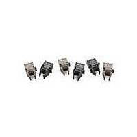
HFBR-1521ETZ Avago Technologies US Inc., HFBR-1521ETZ Datasheet - Page 13

HFBR-1521ETZ
Manufacturer Part Number
HFBR-1521ETZ
Description
FIBER OPTIC TRANSMITTER 660NM
Manufacturer
Avago Technologies US Inc.
Series
Versatile Linkr
Datasheet
1.HFBR-1527ETZ.pdf
(14 pages)
Specifications of HFBR-1521ETZ
Wavelength
660nm
Voltage - Forward (vf) Typ
1.67V
Current - Dc Forward (if)
60mA
Voltage - Dc Reverse (vr) (max)
5V
Capacitance
86pF
Connector Type
Versatile Link
Maximum Forward Current
80 mA
Maximum Power Dissipation
40 mW
Operating Voltage
7 V
Transmission Distance
43 m
Product
Transmitter
Data Rate
5 MBd
Diode Capacitance
86 pF
Maximum Rise Time
20 ns
Maximum Fall Time
20 ns
Pulse Width Distortion
40 ns
Maximum Output Current
250 uA
Operating Supply Voltage
7 V
Maximum Operating Temperature
+ 85 C
Minimum Operating Temperature
- 40 C
Lead Free Status / RoHS Status
Lead free / RoHS Compliant
Spectral Bandwidth
-
Lead Free Status / Rohs Status
Lead free / RoHS Compliant
Other names
516-2301-5
Available stocks
Company
Part Number
Manufacturer
Quantity
Price
Part Number:
HFBR-1521ETZ HFBR-2521ETZ
Manufacturer:
AVAGO/安华高
Quantity:
20 000
HFBR-25X2ETZ Receivers
DO NOT CONNECT
DO NOT CONNECT
Absolute Maximum Ratings
Notes:
1. 1.6 mm below seating plane.
2. It is essential that a bypass capacitor 0.1 PF be connected from pin 2 to pin 3 of the receiver. Total lead length between both ends of the capacitor
3. Moisture sensitivity level is MSL-3
Receiver Electrical/Optical Characteristics
Notes:
1. Optical power measured at the end of 1 mm diameter POF (NA = 0.5) with a large area detector.
2. Pulsed LED operation at I
3. The LED drive circuit of Figure 11 is required for 1 MBd operation of the HFBR-25X2ETZ.
4. Optical flux, P (dBm) = 10 Log [P(PW)/1000 PW].
5. R
13
Parameter
Storage Temperature
Operating Temperature
Lead Soldering Cycle
Supply Voltage
Output Collector Current
Output Collector Power Dissipation
Output Voltage
Pull-up Voltage
Fan Out (TTL)
Parameter
Receiver Optical Input
Power Level Logic 0
Optical Input Power
Level Logic 1
High Level Output Current
Low Level Output Voltage
High Level Supply Current
Low Level Supply Current
Effective Diameter
Internal Pull-up Resistor
and the pins should not exceed 20 mm.
width distortion of the receiver output signal.
L
is open.
5
8
F
> 80 mA will cause increased link t
1000 Ω
Temp.
Time
4
3
2
1
R
V
GROUND
V
Symbol
CC
O
L
P
P
I
I
V
I
CCH
CCL
R(H)
OH
R
R(L)
D
OL
L
-40° to 85° C, 4.75 V ≤V
Min.
680
–24
Symbol
PLH
I
P
V
OAV
V
V
T
T
N
OD
CC
propagation delay time. This extended t
A
S
O
P
1000
Typ.
0.4
3.5
6.2
5
1
Note: Pins 5 and 8 are for mounting and retaining purposes only.
Do not electrically connect these pins.
Pin #
1
2
3
4
5
8
1700
Max.
-9.5
250
-43
0.5
6.3
Min.
–0.5
–0.5
10
–40
–40
–5
CC
≤5.25 V unless otherwise specified.
Units
dBm
dBm
mm
mA
mA
PA
:
V
Function
V
Ground
V
R
Do not connect
Do not connect
O
CC
Max.
L
+85
+85
260
V
10
25
40
18
7
5
CC
V
I
V
I
V
I
P
V
P
V
P
OL
OH
OL
OL
OH
CC
R
R
R
O
CC
= P
= 0
= -12.5 dBm
= 18 V, P
= 8 mA
= 8 mA
= ≤250 μA
= 5.25 V,
d 0.5 V
Conditions
= 5.25 V,
= 5.25 V
PLH
R(L)MIN
time contributes to increased pulse
Units
mW
sec
mA
° C
° C
° C
V
V
V
R
= 0
Reference
Note 1, 3
Note 2
Notes 1, 2, 3
Note 4
Note 5
Note 5
Note 5
Note 5
Ref.


