RDK-251 Power Integrations, RDK-251 Datasheet - Page 9
RDK-251
Manufacturer Part Number
RDK-251
Description
KIT REF DESIGN FOR LNK457D
Manufacturer
Power Integrations
Series
LinkSwitch®-PLr
Datasheet
1.RDK-251.pdf
(60 pages)
Specifications of RDK-251
Current - Output / Channel
350mA
Outputs And Type
1, Isolated
Voltage - Output
12 ~ 18 V
Features
Dimmable
Voltage - Input
90 ~ 265VAC
Utilized Ic / Part
LNK457D
Output Voltage
12 V
Input / Supply Voltage (max)
265 VAC
Input / Supply Voltage (min)
90 VAC
Duty Cycle (max)
39.9 %
Mounting Style
Through Hole
Output Current
350 mA
Output Power
5 W
Lead Free Status / RoHS Status
Lead free / RoHS Compliant
Other names
596-1345
Available stocks
Company
Part Number
Manufacturer
Quantity
Price
Company:

Part Number:
RDK-251
Manufacturer:
Power Integrations
Quantity:
135


15-Feb-11
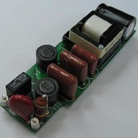
RDR-251 – 5 W, PFC, Dimmable LED Power Supply
4 Circuit Description
This circuit is configured as non-isolated discontinuous flyback converter designed to
drive LED strings at voltages of 12 V to 18 V with an output current of 350 mA. The driver
is guaranteed to operate across a wide range input voltage range and provide high power
factor. The circuit meets both line surge and EMI requirements and the low component
count allows board dimensions required for LED bulb replacement applications.
4.1 Dimming Performance Circuit Design Considerations
The requirement to provide output dimming with low cost, TRIAC base, leading edge
phase dimmers introduces a number of trade offs in the design.
Due to the much lower power consumed by LED based lighting the line current drawn by
the overall lamp is typically below the holding current of the TRIAC within the dimmer.
This causes undesirable behaviors such as limited dim range and/or flickering. The
relatively large impedance the LED driver presents to the line allows significant ringing to
occur when the TRIAC turns on. At the instant the TRIAC conducts, a large inrush current
flows into the input capacitance of the driver, exciting the line inductance and causing
current ringing. This too can cause similar undesirable behavior as the ringing may cause
the TRIAC current to fall to zero and turn off, also generating flicker.
To overcome these issues the circuit includes two circuit blocks labeled active damper
and bleeder. The drawback of these blocks is increased dissipation and therefore
reduced efficiency of the supply.
The values used for the damper and bleeder in this design allow correct operation of a
single board with the widest range of 600 W dimmer models including low cost leading
edge TRIAC models across the full input voltage range. The trade off decision was to
give flicker free operation for a single lamp connected to a dimmer operating at high line.
A single lamp operating at high line results in the lowest current drawn from the line and
the highest inrush current (when the TRIAC fires) and represents the worst case. As a
result the active damper and bleeder networks were designed to be aggressive; lower
impedance for the bleeder and higher impedance for the damper. This increases
dissipation and therefore lowers efficiency of the driver and efficacy of the overall system.
Requiring multiple lamps to be connected to a single dimmer for correct operation
reduces the current required through the bleeder, allowing increasing the values of R10
and R11 and reducing the value of C6.
Limiting operation to low line only (85 VAC to 132 VAC) allows the values of R7 and R8
to be reduced as the peak currents that occur when a leading edge dimmer TRIAC fires
are significantly lower.
Both changes reduce dissipation and improve efficiency.
Power Integrations
Tel: +1 408 414 9200 Fax: +1 408 414 9201
Page 9 of 60
www.powerint.com
Related parts for RDK-251
Image
Part Number
Description
Manufacturer
Datasheet
Request
R

Part Number:
Description:
KIT REF DESIGN TOP HX FOR TOP258
Manufacturer:
Power Integrations
Datasheet:

Part Number:
Description:
KIT REF DESIGN LINKSWITCH 2
Manufacturer:
Power Integrations
Datasheet:

Part Number:
Description:
KIT REF DESIGN 1.2W PS TN FAMILY
Manufacturer:
Power Integrations
Datasheet:

Part Number:
Description:
KIT REF DESIGN 36-72W MOTOR DRVR
Manufacturer:
Power Integrations
Datasheet:

Part Number:
Description:
REFERENCE DESIGN LINKSWITCH-PH
Manufacturer:
Power Integrations
Datasheet:

Part Number:
Description:
Specifications: Manufacturer: Power Integrations ; Output Voltage: 380 VDC ; Input / Supply Voltage (Max): 264 VAC ; Input / Supply Voltage (Min): 90 VAC ; Mounting Style: Through Hole ; Output Current: 0.913 A ; Output Power: 347 W
Manufacturer:
Power Integrations, Inc.

Part Number:
Description:
Power Management Modules & Development Tools TOPSwitch-JX REF. DESIGN KIT
Manufacturer:
Power Integrations
Datasheet:
Part Number:
Description:
Power Management IC Development Tools REF DESIGN RDR-292 PFF LED STREET LIGHT
Manufacturer:
Power Integrations

Part Number:
Description:
KIT REF DESIGN FOR LNK403EG
Manufacturer:
Power Integrations
Datasheet:

Part Number:
Description:
KIT REF DESIGN FOR LNK406EG
Manufacturer:
Power Integrations
Datasheet:
Part Number:
Description:
KIT REF DESIGN 36-72W MOTOR DRVR
Manufacturer:
Power Integrations
Datasheet:
Part Number:
Description:
REFERENCE DESIGN LINKSWITCH-PH
Manufacturer:
Power Integrations
Datasheet:
Part Number:
Description:
Specifications: Manufacturer: Power Integrations ; Output Voltage: 380 VDC ; Input / Supply Voltage (Max): 264 VAC ; Input / Supply Voltage (Min): 90 VAC ; Mounting Style: Through Hole ; Output Current: 0.913 A ; Output Power: 347 W
Manufacturer:
Power Integrations, Inc.
Part Number:
Description:
Specifications: Family: Eval Boards - DC/DC & AC/DC (Off-Line) SMPS ; Series: HiperLCS™ ; Main Purpose: DC/DC, Step Down ; Outputs and Type: 1, Isolated ; Power - Output: 150W ; Voltage - Output: 24V ; Current - Output: 6.25A ; Voltage - Input:
Manufacturer:
Power Integrations, Inc.
Datasheet: