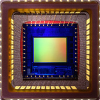
MT9V131C12STC Aptina LLC, MT9V131C12STC Datasheet - Page 4

MT9V131C12STC
Manufacturer Part Number
MT9V131C12STC
Description
SENSOR IMAGE VGA COLOR 48CLCC
Manufacturer
Aptina LLC
Series
Micron®DigitalClarity®r
Type
CMOS Imagingr
Datasheet
1.MT9V131C12STC.pdf
(14 pages)
Specifications of MT9V131C12STC
Package / Case
48-CLCC
Pixel Size
5.6µm x 5.6µm
Active Pixel Array
640H x 480V
Frames Per Second
15 ~ 90
Voltage - Supply
2.8V
Supply Voltage Range
2.55V To 3.05V
Operating Temperature Range
-20°C To +60°C
Digital Ic Case Style
CLCC
No. Of Pins
48
Supply Voltage Max
3.05V
Supply Voltage
RoHS Compliant
Ic Function
Digital Image Sensor
Rohs Compliant
Yes
Lead Free Status / RoHS Status
Lead free / RoHS Compliant
For Use With
557-1243 - KIT HEADBOARD FOR MT9V131557-1242 - KIT DEMO FOR MT9V131
Lead Free Status / RoHS Status
Lead free / RoHS Compliant
Other names
557-1241
Figure 3:
PDF: 09005aef824c99b3/Source: 009005aef824c99bb
MT9V131_LDS_2.fm - Rev. B 3/07 EN
Typical Configuration (Connection)
Note:
Figure 3 shows MT9V131 typical connections. For low-noise operation, the MT9V131
requires separate supplies for analog and digital power. Incoming digital and analog
ground conductors can be tied together right next to the die. Both power supply rails
should be decoupled to ground using capacitors. The use of inductance filters is not
recommended.
T wo-wir e
serial bus
1.5KΩ
For two-wire serial interface, a 1.5KΩ resistor is recommended, but may be greater for
slower two-wire speed.
{
1.5KΩ
1KΩ
V
Master
MT9V131: 1/4-Inch SOC VGA CMOS Digital Image Sensor
DD
Clock
10µF
D
GND
SCAN_EN
S
RESET#
S
SCLK
CLKIN
OE#
S T ANDB Y
ADDR
DATA
4
V
AA
A
GND
Micron Technology, Inc., reserves the right to change products or specifications without notice.
FRAME_ V ALI D
LINE_ V ALI D
D
OUT
PIXCLK
FLASH
(7:0)
{
T o Xenon flas h
trigger or LED enable
T o CMO S
camera port
General Description
©2006 Micron Technology, Inc. All rights reserved.
Preliminary


