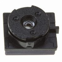
VS6502V015/T2 STMicroelectronics, VS6502V015/T2 Datasheet - Page 18

VS6502V015/T2
Manufacturer Part Number
VS6502V015/T2
Description
SENSOR COLOR VGA CMOS SMOP
Manufacturer
STMicroelectronics
Type
CMOS Imagingr
Datasheet
1.VS6502V015T2.pdf
(48 pages)
Specifications of VS6502V015/T2
Pixel Size
5.6µm x 5.6µm
Active Pixel Array
644H x 484V
Frames Per Second
30
Voltage - Supply
2.6 V ~ 3.6 V
Package / Case
SMOP2
Lead Free Status / RoHS Status
Lead free / RoHS Compliant
Other names
497-3884-1
Available stocks
Company
Part Number
Manufacturer
Quantity
Price
Part Number:
VS6502V015/T2
Manufacturer:
ST
Quantity:
20 000
Functional Description
2.5
Warning:Entering RUN mode directly from SLEEP does not give the analogue circuitry in the sensor enough
Note:
2.5.1
2.5.2
18/48
Mode Control
The VS6502 modes are controlled by two I2C registers:
On power up, the VS6502 is in low-power mode and bit 0 of register [16] is set. Clearing this bit via
the I2C interface causes the VS6502 to go directly into RUN mode and start producing video data.
time to stabilise before video data is produced. The first few frames of video data will not appear to
be correctly exposed. For streaming video applications this may be perfectly acceptable but this
could cause problems for systems which wish to capture and use the first video frame output from
the sensor.
In order to guarantee a valid first video frame it is necessary to enter IDLE mode to allow the
analogue circuitry to be powered on. The sensor must remain in IDLE mode for at least 10 ms.
IDLE mode may be entered from SLEEP mode as follows:
The transition from IDLE to RUN is now controlled by bit 1 of register[28].
The first video frame will appear (along with the first FST pulse) one exposure time after the sensor
goes into RUN mode.
The default value of exposure is maximum (ie 1/30th second) but may be changed as required.
Standby mode (CHIPEN high)
Standby mode is entered asynchronously by driving the CHIPEN pin high. In this mode the
analogue blocks of the sensor are powered down and the video timing logic is reset with all data
lines driven high.The external sensor clock is gated and no I2C communication is possible. To
achieve absolute minimum power consumption, the external clock should be switched off. During
standby mode the register contents are preserved.
Sensor reset via the serial interface
It is possible to completely reset the VS6502 via the serial interface by setting bit 1 of the SETUP0
register. This will reset all the VS6502 registers.
Register[16] - Setup0
Register[28] - IDLE mode control
set bits 0 and 1 of register[28]
clear bit 0 of register[16]
VS6502


