GP2S24 Sharp Microelectronics, GP2S24 Datasheet

PHOTOINTERRUPTER REFLEC .8MM DIP

GP2S24

Manufacturer Part Number
GP2S24
Description
PHOTOINTERRUPTER REFLEC .8MM DIP
Manufacturer
Sharp Microelectronics
Datasheet

Specifications of GP2S24

Operating Temperature
-25°C ~ 85°C
Sensing Distance
0.031" (0.8mm)
Sensing Method
Reflective
Voltage - Collector Emitter Breakdown (max)
35V
Current - Collector (ic) (max)
20mA
Current - Dc Forward (if)
50mA
Output Type
Phototransistor
Response Time
20µs, 20µs
Mounting Type
Through Hole
Package / Case
PCB Mount
Lead Free Status / RoHS Status
Contains lead / RoHS non-compliant
Other names
425-1093-5

Available stocks

Company
Part Number
Manufacturer
Quantity
Price
Part Number:
GP2S24
Manufacturer:
PERKINELMER
Quantity:
1
Part Number:
GP2S24B
Manufacturer:
KODENSHI
Quantity:
12 660
Part Number:
GP2S24BJ000F
Manufacturer:
IXYS
Quantity:
45
Part Number:
GP2S24CJ000F
Manufacturer:
MURATA
Quantity:
360 000
Part Number:
GP2S24J0000F
Manufacturer:
WEITRONY
Quantity:
12 604
GP2S09/GP2S24/
GP2S26/GP2S27
1. Compact and thin
2. Optimum detection distance: 0.6 to 0.8mm
3. Visible light cut-off type
“ In the absence of confirmation by device specification sheets, SHARP takes no responsibility for any defects that occur in equipment using any of SHARP's devices, shown in catalogs,
data books, etc. Contact SHARP in order to obtain the latest version of the device specification sheets before using any SHARP's device.”
GP2S09
GP2S26
4 - 0.5
GP2S09
GP2S24
GP2S26: Flat lead type
GP2S27: Mini-flat package type
C0.7
Outline Dimensions
Features
4 - ( 0.6 )
( ) : Reference dimensions
Tolerance:± 0.15mm
The dimensions indicated by
to those measured from the lead base.
C0.7
4
1
± 20 ˚
+ 0.2
- 0.1
0.4
1.75
4
1
0.4
4.0
+ 0.2
- 0.1
( ) : Reference dimensions
1.75
Tolerance:± 0.15mm
+ 0.2
- 0.1
: Compact DIP long lead type
: Compact DIP type
+0.2
- 0.1
3
2
±15˚
3
2
13.0
3.0
4 - 0.2
3.0
4.0
( 4.0 )
+ 0.2
- 0.1
± 1.0
+ 0.2
- 0.1
refer
± 0.2
+ 0.3
- 0
: 0 to 20˚
4 - 0.4
GP2S24
GP2S27
C0.7
( ) : Reference dimensions
Tolerance:± 0.15mm
The dimensions indicated by
+ 0.2
- 0.1
to those measured from the lead base.
4
1
4.0
2
3
4.0
( ) : Reference dimensions
Tolerance:± 0.15mm
1.75
+ 0.2
± 15 ˚
- 0.1
+ 0.2
- 0.1
1.75
3
2
1
4
0.4
C0.7
4 - 0.15
+ 0.2
- 0.1
1. Cassette tape recorders, VCRs
2. Floppy disk drives
3. Various microcomputerized control equip-
3.0
Applications
ment
4.0
( 4.0 )
: 0 to 20˚
+ 0.2
- 0.1
3.0
5.0
± 0.2
( 0.4 )
refer
+ 0.2
- 0.1
MAX.
GP2S09/GP2S24/GP2S26/GP2S27
4
1
Internal connection diagram
( Common to 4 models )
Subminiature
Photointerrupter
1 Anode
2 Emitter
3 Collector
4 Cathode
( Unit : mm )
3
2

Related parts for GP2S24

GP2S24 Summary of contents

Page 1

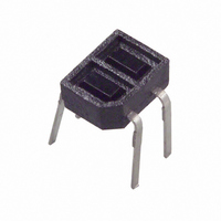
... The dimensions indicated by refer to those measured from the lead base. GP2S27 1.75 + 0.2 + 0.2 3.0 4.0 - 0.1 - 0.1 ( 0.4 ) 0.4 MAX. 5.0 Tolerance:± 0.15mm ( ) : Reference dimensions GP2S09/GP2S24/GP2S26/GP2S27 Subminiature Photointerrupter ( Unit : mm ) Internal connection diagram ( Common to 4 models ) Anode 2 Emitter 3 Collector 4 Cathode ...

Page 2

... The condition and arrangement of the reflective object are shown below. 4 Without reflective object The ranking of collector current shall be classi- fied into the following 6 ranks. ( GP2S09, GP2S24, GP2S26, GP2S27 ) ( A ) Rank Collector-current 120 120 120 5 GP2S24 and GP2S26 and GP2S27 don't have A rank. Symbol Rating CEO V 6 ECO ...

Page 3

... Collector-emitter voltage V Fig. 2 Power Dissipation vs 100 ( ˚ Fig. 4 Collector Current vs. 0˚C - 25˚C 2.5 3 Fig. 6 Relatlve Collector Current vs GP2S09/GP2S24/GP2S26/GP2S27 Ambient Temperature 120 P tot 100 ˚C ) Ambient temperature T a Forward Current 700 25˚C a 600 500 ...

Page 4

... Fig. 7 Collector Dark Current vs. Ambient Temperature - 20V Ambient temperature T Fig. 9 Response Time vs. Load Resistance ( GP2S24/ GP2S26/GP2S27 ) 1000 500 I = 100 A C 200 T = 25˚ 100 0.5 0.2 0.1 0 Load resistance R L Fig.10 Relative Collector Current vs. Distance between Sensor and Al Evaporation Glass 100 ...

Page 5

... R = 10k Frequency Fig.14 Spectral Sensitivity ( Detecting Side ) 100 600 700 800 900 1000 ( nm ) Wavelength Test Condition for Distance & Detecting Position Characteristics ( EX : GP2S24 ) Correspond to Fig. 4mA 1mm T = 25˚C a Correspond to Fig.11 Test condition I = 4mA 1mm Fig.13-b Frequency Response ( GP2S09 ) 100 25˚C ...

Page 6

Application Circuits NOTICE The circuit application examples in this publication are provided to explain representative applications of SHARP devices and are not intended to guarantee any circuit design or license any intellectual property rights. SHARP takes no responsibility for any ...

Related keywords