2831C B&K Precision, 2831C Datasheet - Page 13
2831C
Manufacturer Part Number
2831C
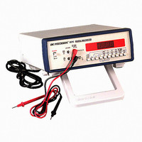
Description
DMM BENCH 3 1/2 DIGIT TRUE RMS
Manufacturer
B&K Precision
Type
Digital (DMM)r
Specifications of 2831C
Includes
Test Leads
Style
Bench
Display Digits
3.5
Display Type
LED
Display Count
2000
Function
Voltage, Current, Resistance
Functions, Extra
Continuity, Diode Test
Response
True RMS
Features
-
Ranging
-
Lead Free Status / Rohs Status
Lead free / RoHS Compliant
Other names
BK2831C


CURREN T MEA SURE ME NTS
2. Select ac or dc measurement using the AC/DC switch. Set for
3. If the current to be measured is unknown. start with the meter
1. Press the A function switch.
dc measurement by setting switch to
switch "in" for ac measurement.
might exceed 2 A, use high current test leads.
in the 20 A range, using the 20 A jack. If the expected current
protection and moy severely damage the
personal injury.
For current meqsurements, the meter must
be connected in series wilh the load. If
load), the meter presents a very low
the fuse or damage the meter or equipment
under test. The 20 A range has on fuse
meter or equipment under test or cause
For current meesurements greater thun 2 A,
high curent test leads should be used. High
current measurements with standard test
leads could cause the leads to heat up. This
nol
meqsurement, but could result in injury to
the operator.
incorrectly connected (in parallel with the
impedance (almost a short), which may blow
only affects the accuracy of the
"out" position. Push
s
4.lf m approximate current range is known, simply press the
5. Remove power from the circuit rurder measurement and open the
6. Apply porver to the circuit and read the measured value on the
RESISTANCE M EASU REMENTS
2. Press the fJ function switch.
3. Connect the red test lead to the V -O jack and black test
4. Connect the test leads to the desired point of measurement
5. If the expected resistance range is unknown, start with the
L Remove power from the equipment under test.
the range closest to an overange for the current being measured.
b. For curent measurements greater than 2 A, connect ared high
normal circuit path where the measurement is to be taken.
switch for the range desired. Greatest resolution is attained using
a. For current measurements of 2 A or less, connect the red test
Connect the metsr in serles with the circuit.
display.
lead to the COM jack. The red lead is (+) polarity.
and observe the reading on the display.
selecting higher ranges until the overrange indication
ceases. At this range, greatest resolution is achieved.
lowest range. If an overrange is indicated, continue
lead to the 2 A jack and the black test lead to the COM jack.
current test lead to the 20 Ajack and connect ablack high
cuftent test lead to the COM jack.
OPERATING INSTRUCTIONS