MBR10100CT/45 Vishay, MBR10100CT/45 Datasheet - Page 3
MBR10100CT/45
Manufacturer Part Number
MBR10100CT/45
Description
Schottky (Diodes & Rectifiers) 10 Amp 100 Volt
Manufacturer
Vishay
Datasheet
1.MBR10100CT-E345.pdf
(5 pages)
Specifications of MBR10100CT/45
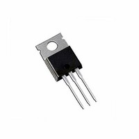
Package / Case
TO-220AB
Product
Schottky Diodes
Peak Reverse Voltage
100 V
Forward Continuous Current
5 A
Max Surge Current
120 A
Configuration
Dual Common Cathode
Forward Voltage Drop
0.85 V
Maximum Reverse Leakage Current
100 uA
Operating Temperature Range
- 65 C to + 150 C
Mounting Style
Through Hole
Peak Reflow Compatible (260 C)
No
Current Rating
10A
Leaded Process Compatible
No
Mounting Type
Through Hole
Lead Free Status / RoHS Status
Lead free / RoHS Compliant


Document Number: 89125
Revision: 26-Apr-10
Figure 4. Typical Instantaneous Forward Characteristics Per Diode
0.0001
Figure 3. Forward Power Loss Characteristics Per Diode
0.001
100
0.01
100
4.0
3.5
3.0
2.5
0.1
2.0
1.5
1.0
0.5
10
Figure 5. Typical Reverse Characteristics Per Diode
0.1
10
0
1
1
0
0
0
T
Percent of Rated Peak Reverse Voltage (%)
A
0.2
= 125 °C
T
D = 0.1
T
Instantaneous Forward Voltage (V)
A
1
A
T
= 150 °C
20
= 150 °C
A
Average Forward Current (A)
0.4
= 100 °C
D = 0.2
T
T
A
2
A
0.6
= 25 °C
D = 0.3
= 125 °C
40
DiodesAmericas@vishay.com, DiodesAsia@vishay.com,
T
0.8
For technical questions within your region, please contact one of the following:
3
A
= 25 °C
D = 0.5
T
A
D = t
60
1.0
= 100 °C
D = 0.8
4
p
/T
1.2
80
T
5
t
D = 1.0
p
1.4
1.6
100
6
10 000
Figure 7. Typical Transient Thermal Impedance Per Diode
1000
100
0.1
10
10
Figure 6. Typical Junction Capacitance Per Diode
0.01
MBR1090CT, MBR10100CT
0.1
DiodesEurope@vishay.com
Vishay General Semiconductor
Junction to Case
0.1
t - Pulse Duration (s)
Reverse Voltage (V)
1
1
10
T
f = 1 MHz
V
J
sig
10
= 25 °C
= 50 mVp-p
www.vishay.com
100
100
3
Related parts for MBR10100CT/45
Image
Part Number
Description
Manufacturer
Datasheet
Request
R

Part Number:
Description:
High-Voltage Schottky Rectifier
Manufacturer:
VISHAY [Vishay Siliconix]
Datasheet:

Part Number:
Description:
DIODE SCHOTT 10A 100V SGL TO220
Manufacturer:
Vishay
Datasheet:


Part Number:
Description:
Schottky (Diodes & Rectifiers) 10 Amp 100 Volt
Manufacturer:
Vishay
Datasheet:

Part Number:
Description:
357-036-542-201 CARDEDGE 36POS DL .156 BLK LOPRO
Manufacturer:
Vishay
Datasheet:
Part Number:
Description:
357-036-542-201 CARDEDGE 36POS DL .156 BLK LOPRO
Manufacturer:
Vishay
Datasheet:
Part Number:
Description:
357-036-542-201 CARDEDGE 36POS DL .156 BLK LOPRO
Manufacturer:
Vishay
Datasheet:
Part Number:
Description:
357-036-542-201 CARDEDGE 36POS DL .156 BLK LOPRO
Manufacturer:
Vishay
Datasheet:
Part Number:
Description:
357-036-542-201 CARDEDGE 36POS DL .156 BLK LOPRO
Manufacturer:
Vishay
Datasheet:
Part Number:
Description:
357-036-542-201 CARDEDGE 36POS DL .156 BLK LOPRO
Manufacturer:
Vishay
Datasheet:
Part Number:
Description:
357-036-542-201 CARDEDGE 36POS DL .156 BLK LOPRO
Manufacturer:
Vishay
Datasheet:
Part Number:
Description:
357-036-542-201 CARDEDGE 36POS DL .156 BLK LOPRO
Manufacturer:
Vishay
Datasheet:
Part Number:
Description:
357-036-542-201 CARDEDGE 36POS DL .156 BLK LOPRO
Manufacturer:
Vishay
Datasheet:
Part Number:
Description:
357-036-542-201 CARDEDGE 36POS DL .156 BLK LOPRO
Manufacturer:
Vishay
Datasheet: