1N5819 ON Semiconductor, 1N5819 Datasheet
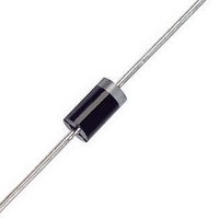
Schottky (Diodes & Rectifiers) 1A 40V

1N5819

Manufacturer Part Number
1N5819
Description
Schottky (Diodes & Rectifiers) 1A 40V
Manufacturer
ON Semiconductor
Datasheet

Specifications of 1N5819

Product
Schottky Diodes
Peak Reverse Voltage
40 V
Forward Continuous Current
1 A @ Ta=55C
Max Surge Current
25 A
Configuration
Single
Forward Voltage Drop
0.9 V @ 3 A
Maximum Reverse Leakage Current
1000 uA
Operating Temperature Range
- 65 C to + 125 C
Mounting Style
Through Hole
Package / Case
DO-41
Lead Free Status / RoHS Status
Lead free / RoHS Compliant

Available stocks

Company
Part Number
Manufacturer
Quantity
Price
Part Number:
1N5819
Manufacturer:
WEJ
Quantity:
982
Part Number:
1N5819
Manufacturer:
TOSHIBA
Quantity:
4 200
Part Number:
1N5819
Manufacturer:
TOSHIBA
Quantity:
56 000
Part Number:
1N5819
Quantity:
1 950
Part Number:
1N5819
Manufacturer:
MICREL/麦瑞
Quantity:
20 000
Part Number:
1N5819 @@@@@@@
Manufacturer:
ST
0
Part Number:
1N5819 S4
Manufacturer:
ST
0
Part Number:
1N5819 S4
Manufacturer:
CJ/长电
Quantity:
20 000
Part Number:
1N5819 SOD-123
Manufacturer:
ST
0
Part Number:
1N5819 SS14
Manufacturer:
TOSHIBA/东芝
Quantity:
20 000
Part Number:
1N5819 ST
Manufacturer:
ST
0
Part Number:
1N5819-1JANTX
Manufacturer:
HITTITE
Quantity:
1 400
Part Number:
1N5819-5255M
Manufacturer:
MICREL/麦瑞
Quantity:
20 000
Part Number:
1N5819-5260M
Manufacturer:
KSY
Quantity:
20 000
Part Number:
1N5819-E3/54
Manufacturer:
VISHAY
Quantity:
150
Company:
Part Number:
1N5819-E3/54
Quantity:
16 500
1N5817, 1N5818, 1N5819
Axial Lead Rectifiers
metal−to−silicon power diode. State−of−the−art geometry features
chrome barrier metal, epitaxial construction with oxide passivation
and metal overlap contact. Ideally suited for use as rectifiers in
low−voltage, high−frequency inverters, free wheeling diodes, and
polarity protection diodes.
Features
Mechanical Characteristics:
*For additional information on our Pb−Free strategy and soldering details, please
© Semiconductor Components Industries, LLC, 2006
July, 2006 − Rev. 10
download the ON Semiconductor Soldering and Mounting Techniques
Reference Manual, SOLDERRM/D.
This series employs the Schottky Barrier principle in a large area
Leads are Readily Solderable
260°C Max for 10 Seconds
Extremely Low V
Low Stored Charge, Majority Carrier Conduction
Low Power Loss/High Efficiency
These are Pb−Free Devices*
Case: Epoxy, Molded
Weight: 0.4 Gram (Approximately)
Finish: All External Surfaces Corrosion Resistant and Terminal
Lead Temperature for Soldering Purposes:
Polarity: Cathode Indicated by Polarity Band
ESD Ratings: Machine Model = C (>400 V)
1N5817 and 1N5819 are Preferred Devices
Human Body Model = 3B (>8000 V)
F
1
See detailed ordering and shipping information on page 6 of
this data sheet.
Preferred devices are recommended choices for future use
and best overall value.
(Note: Microdot may be in either location)
SCHOTTKY BARRIER
20, 30 and 40 VOLTS
ORDERING INFORMATION
A
1N581x =Device Number
YY
WW
G
MARKING DIAGRAM
http://onsemi.com
RECTIFIERS
1.0 AMPERE
=Assembly Location
=Year
=Work Week
=Pb−Free Package
x= 7, 8, or 9
YYWWG
1N581x
Publication Order Number:
A
G
AXIAL LEAD
CASE 59
STYLE 1
1N5817/D

Related parts for 1N5819

1N5819 Summary of contents

Page 1

... Preferred Devices Axial Lead Rectifiers This series employs the Schottky Barrier principle in a large area metal−to−silicon power diode. State−of−the−art geometry features chrome barrier metal, epitaxial construction with oxide passivation and metal overlap contact. Ideally suited for use as rectifiers in low− ...

Page 2

... Thermal Resistance, Junction−to−Ambient ELECTRICAL CHARACTERISTICS Characteristic Maximum Instantaneous Forward Voltage (Note 2) Maximum Instantaneous Reverse Current @ Rated dc Voltage (Note 2) 1. Lead Temperature reference is cathode lead 1/32 in from case. 2. Pulse Test: Pulse Width = 300 ms, Duty Cycle = 2.0%. 1N5817, 1N5818, 1N5819 ≤ 0.2 V (dc 90°C, R(equiv 55° ...

Page 3

... Half Wave Circuit Load Resistive Capacitive* Sine Wave 0.5 Square Wave 0.75 ≈ 2.0 V **Note that V . R(PK) in(PK) 1N5817, 1N5818, 1N5819 125 ° 115 (1) 105 P qJA R(AV 2.0 Figure 1. Maximum Reference Temperature (2) R(AV) ...

Page 4

... TYPICAL VALUES FOR R qJA Lead Length, L (in) Mounting Method 1/8 1/4 1 1N5817, 1N5818, 1N5819 5.0 Sine Wave = π (Resistive Load) I 3.0 (FM) I 2.0 (AV) Capacitive 1.0 Loads 0.7 0.5 TYPICAL 0.3 0.2 0.1 0.07 ...

Page 5

... INSTANTANEOUS FORWARD VOLTAGE (VOLTS) F Figure 7. Typical Forward Voltage 1N5817, 1N5818, 1N5819 NOTE 5. — THERMAL CIRCUIT MODEL (For heat conduction through the leads qL(A) qJ(A) qJ(K) qL( L(A) C(A) ...

Page 6

... Tape and Reel Packaging Specifications Brochure, BRD8011/D. *This package is inherently Pb−Free. 1N5817, 1N5818, 1N5819 200 100 1.0 MHz 10 ...

Page 7

... Literature Distribution Center for ON Semiconductor P.O. Box 5163, Denver, Colorado 80217 USA Phone: 303−675−2175 or 800−344−3860 Toll Free USA/Canada Fax: 303−675−2176 or 800−344−3867 Toll Free USA/Canada Email: orderlit@onsemi.com 1N5817, 1N5818, 1N5819 PACKAGE DIMENSIONS AXIAL LEAD CASE 59−10 ISSUE U NOTES: 1 ...

Related keywords