BAS40-06-TP Micro Commercial Components (MCC), BAS40-06-TP Datasheet - Page 3
BAS40-06-TP
Manufacturer Part Number
BAS40-06-TP
Description
DIODE SCHOTTKY 40V 200MA SOT23
Manufacturer
Micro Commercial Components (MCC)
Specifications of BAS40-06-TP
Voltage - Forward (vf) (max) @ If
1V @ 40mA
Current - Reverse Leakage @ Vr
200nA @ 30V
Current - Average Rectified (io) (per Diode)
200mA (DC)
Voltage - Dc Reverse (vr) (max)
40V
Reverse Recovery Time (trr)
5ns
Diode Type
Schottky
Speed
Small Signal =< 200mA (Io), Any Speed
Diode Configuration
1 Pair Common Anode
Mounting Type
Surface Mount
Package / Case
SOT-23
Product
Schottky Diodes
Peak Reverse Voltage
40 V
Forward Continuous Current
0.2 A
Max Surge Current
0.6 A
Configuration
Dual Common Anode
Recovery Time
5 ns
Forward Voltage Drop
1 V at 0.04 A
Maximum Reverse Leakage Current
0.2 uA
Mounting Style
SMD/SMT
Capacitance, Junction
5 pF
Current, Forward
200 mA
Current, Reverse
20 nA
Current, Surge
600 mA
Package Type
SOT-23
Power Dissipation
200 mW
Primary Type
Schottky Barrier
Temperature, Junction, Maximum
+125 °C
Temperature, Operating
-55 to +125 °C
Time, Recovery
5 ns
Voltage, Forward
1000 mV
Voltage, Reverse
40 V
Lead Free Status / RoHS Status
Lead free / RoHS Compliant
Lead Free Status / RoHS Status
Lead free / RoHS Compliant, Lead free / RoHS Compliant
Other names
BAS40-06TPMSTR


ELECTRICAL CHARACTERISTICS PER DIODE @ 25
BAS40
BAS40-04
BAS40-05
BAS40-06
BAS70
BAS70-04
BAS70-05
BAS70-06
BAS40 and BAS70
DEVICE
TYPE
Figure 1
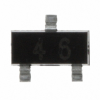
MARKING
DEVICE
43
44
45
46
73
74
75
76
FIGURE
1
2
3
4
1
2
3
4
Peak Reverse
Repetitive
(VOLTS)
Voltage
V
TYP
40
40
40
40
70
70
70
70
RRM
Figure 2
Tested with
10µA Pulse
Breakdown
(VOLTS)
Reverse
Voltage
V
MIN
(BR)R
40
40
40
40
70
70
70
70
Leakage Current
tp < 300µs @
TYP
20
20
20
20
20
20
20
20
For BAS40
For BAS70
Pulse test
V
V
R
R
I
R
= 30 V
= 50 V
(nA)
MAX
200
200
200
200
200
200
200
200
2 of 3
I
Forward Voltage Pulse Test
F
=1mA
0
380
380
380
380
410
410
410
410
C Unless otherwise specified
Figure 3
at I
at I
tp < 300µs
I
V
F
F
F
1000
1000
1000
1000
=15mA I
F
= 1 mA
= 40 mA
(mV)
F
=40mA
1000
1000
1000
1000
I
I
Time from
R
Recovery
F
Reverse
=10mA to
I
through
= 10 mA
R
t
rr
MAX
=1mA
(ns)
5
5
5
5
5
5
5
5
Micro Commercial Components
M C C
Figure 4
Ambient Air
Resistance
R
Junction to
Thermal
thJA
MAX
430
430
430
430
430
430
430
430
(K/W)
Capacitance
At V
F = 1 MHz
MAX
C
pF
R
5
5
5
5
2
2
2
2
tot
= 0V
TM
Related parts for BAS40-06-TP
Image
Part Number
Description
Manufacturer
Datasheet
Request
R

Part Number:
Description:
DIODE SCHOTTKY 40V 200MA SOT23
Manufacturer:
Micro Commercial Components (MCC)
Datasheet:

Part Number:
Description:
DIODE SCHOTTKY 40V 200MA SOT23
Manufacturer:
Micro Commercial Components (MCC)
Datasheet:

Part Number:
Description:
DIODE SCHOTTKY 40V 200MA SOT23
Manufacturer:
Micro Commercial Components (MCC)
Datasheet:

Part Number:
Description:
Schottky (Diodes & Rectifiers) 200mA 40V
Manufacturer:
Micro Commercial Components (MCC)
Datasheet:
Part Number:
Description:
Schottky (Diodes & Rectifiers) 200mA 40V
Manufacturer:
Micro Commercial Components (MCC)
Datasheet:
Part Number:
Description:
Schottky (Diodes & Rectifiers) 200mA 40V
Manufacturer:
Micro Commercial Components (MCC)
Datasheet:
Part Number:
Description:
Schottky (Diodes & Rectifiers) 200mA 40V
Manufacturer:
Micro Commercial Components (MCC)
Datasheet:


Part Number:
Description:
Manufacturer:
Micro Commercial Components (MCC)
Datasheet:
Part Number:
Description:
Manufacturer:
Micro Commercial Components (MCC)
Datasheet:
Part Number:
Description:
Manufacturer:
Micro Commercial Components (MCC)
Datasheet:
Part Number:
Description:
Manufacturer:
Micro Commercial Components (MCC)
Datasheet:
Part Number:
Description:
Manufacturer:
Micro Commercial Components (MCC)
Datasheet:
Part Number:
Description:
Manufacturer:
Micro Commercial Components (MCC)
Datasheet:
Part Number:
Description:
Manufacturer:
Micro Commercial Components (MCC)
Datasheet: