111MT80KPBF Vishay, 111MT80KPBF Datasheet - Page 5
111MT80KPBF
Manufacturer Part Number
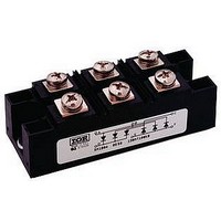
111MT80KPBF
Description
SCR Modules 800 Volt 110 Amp
Manufacturer
Vishay
Specifications of 111MT80KPBF
Mounting Style
Screw
Leaded Process Compatible
Yes
Package / Case
INT-A-Pak
Lead Free Status / RoHS Status
Lead free / RoHS Compliant


Document Number: 94353
Revision: 13-Aug-08
94353_04
94353_05
94353_08a
350
300
250
200
150
400
350
300
250
200
150
300
250
200
150
100
50
0
0.01
Fig. 4 - Maximum Non-Repetitive Surge Current
Fig. 5 - Maximum Non-Repetitive Surge Current
1
0
9.MT..K Series
T
5.MT..K Series
Per junction
5.MT..K Series
Per junction
J
10
= 125 °C
Number of Equal Amplitude Half
20
Cycle Current Pulses (N)
Maximum non-repetitive surge current
Total Output Current (A)
of conduction may not be maintained.
Pulse Train Duration (s)
At any rated load condition and with
rated V
versus pulse train duration. Control
30
RRM
40
(Rect.)
120°
0.1
10
applied following surge.
50
Initial T
No voltage reapplied
Rated V
Initial T
at 60 Hz 0.0083 s
at 50 Hz 0.0100 s
60
J
5.MT...KPbF, 9.MT...KPbF, 11.MT...KPbF Series
For technical questions, contact:
(Power Modules), 55 A to 110 A
RRM
Three Phase Controlled Bridge
= 125 °C
70
J
reapplied
= 125 °C
80
Fig. 8 - Total Power Loss Characteristics
100
90
1
94353_06
94353_07
94353_08b
indmodules@vishay.com
1000
130
120
110
100
100
300
250
200
150
100
10
90
80
50
0
1
0.5
0
Fig. 7 - Forward Voltage Drop Characteristics
0
~
Fig. 6 - Current Ratings Characteristic
1.0
Vishay High Power Products
Maximum Allowable Ambient
20
25
Total Output Current (A)
Total Output Current
1.5
Temperature (°C)
40
50
2.0
+
-
T
T
J
J
= 25 °C
= 125 °C
2.5
(Rect.)
120°
60
75
9.MT..K Series
9.MT..K Series
Per junction
3.0
100
80
3.5
www.vishay.com
100
125
4.0
5
Related parts for 111MT80KPBF
Image
Part Number
Description
Manufacturer
Datasheet
Request
R

Part Number:
Description:
357-036-542-201 CARDEDGE 36POS DL .156 BLK LOPRO
Manufacturer:
Vishay
Datasheet:
Part Number:
Description:
357-036-542-201 CARDEDGE 36POS DL .156 BLK LOPRO
Manufacturer:
Vishay
Datasheet:
Part Number:
Description:
357-036-542-201 CARDEDGE 36POS DL .156 BLK LOPRO
Manufacturer:
Vishay
Datasheet:
Part Number:
Description:
357-036-542-201 CARDEDGE 36POS DL .156 BLK LOPRO
Manufacturer:
Vishay
Datasheet:
Part Number:
Description:
357-036-542-201 CARDEDGE 36POS DL .156 BLK LOPRO
Manufacturer:
Vishay
Datasheet:
Part Number:
Description:
357-036-542-201 CARDEDGE 36POS DL .156 BLK LOPRO
Manufacturer:
Vishay
Datasheet:
Part Number:
Description:
357-036-542-201 CARDEDGE 36POS DL .156 BLK LOPRO
Manufacturer:
Vishay
Datasheet:
Part Number:
Description:
357-036-542-201 CARDEDGE 36POS DL .156 BLK LOPRO
Manufacturer:
Vishay
Datasheet:
Part Number:
Description:
357-036-542-201 CARDEDGE 36POS DL .156 BLK LOPRO
Manufacturer:
Vishay
Datasheet:
Part Number:
Description:
357-036-542-201 CARDEDGE 36POS DL .156 BLK LOPRO
Manufacturer:
Vishay
Datasheet:
Part Number:
Description:
357-036-542-201 CARDEDGE 36POS DL .156 BLK LOPRO
Manufacturer:
Vishay
Datasheet:
Part Number:
Description:
357-036-542-201 CARDEDGE 36POS DL .156 BLK LOPRO
Manufacturer:
Vishay
Datasheet:
Part Number:
Description:
357-036-542-201 CARDEDGE 36POS DL .156 BLK LOPRO
Manufacturer:
Vishay
Datasheet:
Part Number:
Description:
357-036-542-201 CARDEDGE 36POS DL .156 BLK LOPRO
Manufacturer:
Vishay
Datasheet:
Part Number:
Description:
357-036-542-201 CARDEDGE 36POS DL .156 BLK LOPRO
Manufacturer:
Vishay
Datasheet: