P404 Vishay, P404 Datasheet - Page 3
P404
Manufacturer Part Number
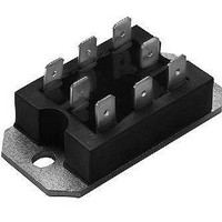
P404
Description
SCR Modules 1000 Volt 40 Amp
Manufacturer
Vishay
Datasheet
1.VS-P402W.pdf
(6 pages)
Specifications of P404
Lead Free Status / RoHS Status
Lead free / RoHS Compliant
Available stocks
Company
Part Number
Manufacturer
Quantity
Price
Company:

Part Number:
P404BSXE1HLB
Manufacturer:
MICRON
Quantity:
1 000
Company:
Part Number:
P404BSXE7HLC
Manufacturer:
FREESCA
Quantity:
2
Company:
Part Number:
P404ELSE1PNB
Manufacturer:
FREESCAL
Quantity:
650
Company:
Part Number:
P404W
Manufacturer:
POWEREX
Quantity:
1 000


Note
(1)
Note
(1)
Document Number: 93755
Revision: 05-Nov-09
TRIGGERING
PARAMETER
Maximum peak gate power
Maximum average gate power
Maximum peak gate current
Maximum peak negative gate voltage
Maximum gate voltage required to trigger
Maximum gate current required to trigger
Maximum gate voltage that will not trigger
Maximum gate current that will not trigger
THERMAL AND MECHANICAL SPECIFICATIONS
PARAMETER
Maximum junction operating
and storage temperature range
Maximum thermal resistance,
junction to case per junction
Maximum thermal resistance,
case to heatsink
Mounting torque, base to heatsink
Approximate weight
CIRCUIT TYPE AND CODING
Terminal positions
Schematic diagram
Basic series
With voltage suppression
With freewheeling diode
With both voltage suppression
and freewheeling diode
A mounting compund is recommended and the torque should be checked after a period of 3 hours to allow for the spread of the compound
To complete code refer to Voltage Ratings table, i.e.: For 600 V P40.W complete code is P402W
(1)
Single phase hybrid bridge
For technical questions, contact:
(-)
(1)
SYMBOL
SYMBOL
common cathode
T
P
R
R
-V
J
CIRCUIT “0”
P
V
I
V
I
, T
G(AV)
I
AC1
AC2
thJC
thCS
GM
GT
GD
GM
GD
GT
GM
AC1
AC2
P40.KW
P40.W
Stg
P40.K
P40.
Passivated Assembled
Circuit Elements, 40 A
1
2
DC operation
Mounting surface, smooth and greased
T
T
T
T
T
T
T
2
J
J
J
J
J
J
J
+
-
1
= - 40 °C
= 25 °C
= 125 °C
= - 40 °C
= 25 °C
= 125 °C
= 125 °C, rated V
(+)
TEST CONDITIONS
TEST CONDITIONS
Single phase hybrid bridge doubler
indmodules@vishay.com
(-)
DRM
Anode supply =
6 V resistive load
CIRCUIT “2”
AC1
AC2
applied
AC2
AC1
1
P42.K
P42.
-
-
1
2
Vishay High Power Products
+
-
2
(+)
- 40 to 125
VALUES
VALUES
Single phase all SCR bridge
1.05
0.10
2.0
(-)
0.2
58
10
90
60
35
8
2
2
3
2
1
2
4
P400 Series
CIRCUIT “3”
AC2
AC1
AC1
AC2
P43.K
3
P43.
1
-
-
4
www.vishay.com
2
3
4
UNITS
UNITS
+
-
2
K/W
Nm
mA
mA
oz.
°C
W
1
A
V
V
V
g
(+)
3
Related parts for P404
Image
Part Number
Description
Manufacturer
Datasheet
Request
R

Part Number:
Description:
357-036-542-201 CARDEDGE 36POS DL .156 BLK LOPRO
Manufacturer:
Vishay
Datasheet:
Part Number:
Description:
357-036-542-201 CARDEDGE 36POS DL .156 BLK LOPRO
Manufacturer:
Vishay
Datasheet:
Part Number:
Description:
357-036-542-201 CARDEDGE 36POS DL .156 BLK LOPRO
Manufacturer:
Vishay
Datasheet:
Part Number:
Description:
357-036-542-201 CARDEDGE 36POS DL .156 BLK LOPRO
Manufacturer:
Vishay
Datasheet:
Part Number:
Description:
357-036-542-201 CARDEDGE 36POS DL .156 BLK LOPRO
Manufacturer:
Vishay
Datasheet:
Part Number:
Description:
357-036-542-201 CARDEDGE 36POS DL .156 BLK LOPRO
Manufacturer:
Vishay
Datasheet:
Part Number:
Description:
357-036-542-201 CARDEDGE 36POS DL .156 BLK LOPRO
Manufacturer:
Vishay
Datasheet:
Part Number:
Description:
357-036-542-201 CARDEDGE 36POS DL .156 BLK LOPRO
Manufacturer:
Vishay
Datasheet:
Part Number:
Description:
357-036-542-201 CARDEDGE 36POS DL .156 BLK LOPRO
Manufacturer:
Vishay
Datasheet:
Part Number:
Description:
357-036-542-201 CARDEDGE 36POS DL .156 BLK LOPRO
Manufacturer:
Vishay
Datasheet:
Part Number:
Description:
357-036-542-201 CARDEDGE 36POS DL .156 BLK LOPRO
Manufacturer:
Vishay
Datasheet:
Part Number:
Description:
357-036-542-201 CARDEDGE 36POS DL .156 BLK LOPRO
Manufacturer:
Vishay
Datasheet:
Part Number:
Description:
357-036-542-201 CARDEDGE 36POS DL .156 BLK LOPRO
Manufacturer:
Vishay
Datasheet:
Part Number:
Description:
357-036-542-201 CARDEDGE 36POS DL .156 BLK LOPRO
Manufacturer:
Vishay
Datasheet:
Part Number:
Description:
357-036-542-201 CARDEDGE 36POS DL .156 BLK LOPRO
Manufacturer:
Vishay
Datasheet: