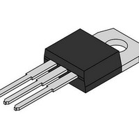
MCR310-010 ON Semiconductor, MCR310-010 Datasheet - Page 2

MCR310-010
Manufacturer Part Number
MCR310-010
Description
SCRs 800V 10A
Manufacturer
ON Semiconductor
Datasheet
1.MCR310-010.pdf
(3 pages)
Specifications of MCR310-010
Breakover Current Ibo Max
100 A
Rated Repetitive Off-state Voltage Vdrm
800 V
Off-state Leakage Current @ Vdrm Idrm
0.01 mA
Forward Voltage Drop
2.2 V
Gate Trigger Voltage (vgt)
1.5 V
Gate Trigger Current (igt)
0.2 mA
Holding Current (ih Max)
6 mA
Mounting Style
Through Hole
Package / Case
TO-220-3
Lead Free Status / RoHS Status
Lead free / RoHS Compliant
Available stocks
Company
Part Number
Manufacturer
Quantity
Price
Company:
Part Number:
MCR310-010
Manufacturer:
ON
Quantity:
8 000
ELECTRICAL CHARACTERISTICS
1. Ratings apply for negative gate voltage or R
2. Does not include R
0.5
0.3
120
100
110
Peak Forward Blocking Current
Peak Reverse Blocking Current
On-State Voltage
Gate Trigger Current, Continuous dc
Gate Trigger Voltage, Continuous dc
Holding Current
Critical Rate of Rise of Forward Blocking Voltage
Gate Controlled Turn-On Time
3
2
1
−40
90
80
70
on the anode. Devices should not be tested with a constant current source for forward and reverse blocking capability such that the
voltage applied exceeds the rated blocking voltage.
(T
(T
(I
(V
(V
(V
(V
(V
(V
0
TM
J
J
D
D
D
D
D
D
= 110 C, V
= 110 C, V
−20
= 12 V, R
= 12 V, R
= Rated V
= 12 V, I
= Rated V
= Rated V
= 20 A Peak, Pulse Width p 1 ms, Duty Cycle p 2%)
Figure 3. Normalized Gate Current
Figure 1. Average Current Derating
= 30
I
T(AV)
0
2
TM
L
L
T
DRM
DRM
DRM
D
R
, AVERAGE ON-STATE CURRENT (AMPS)
= 100 )
= 100 )
J
= 100 mA)
, JUNCTION TEMPERATURE ( C)
= Rated V
= Rated V
20
GK
60
, R
, T
, I
TM
Characteristic
90
current.
J
L
40
= 110 C, Exponential Waveform)
= 10 k , T
= 20 A, I
4
DRM
RRM
60
(1)
(1)
180
)
)
G
J
= 2 mA)
80
(2)
= 110 C)
= CONDUCTION ANGLE
6
(T
V
C
D
90
= 12 Vdc
= 25 C, R
GK
= 1 k . Devices shall not have a positive gate voltage concurrently with a negative voltage
T
T
T
T
100
C
C
C
C
8
= 110 C
= 25 C
= 110 C
= 25 C
GK
120
http://onsemi.com
MCR310 Series
= 1 k
dc
140
10
unless otherwise noted)
2
Symbol
I
I
dv/dt
V
V
DRM
RRM
I
t
GT
I
TM
GT
gt
H
0.7
0.6
0.5
0.4
0.3
0.2
0.1
20
16
12
8
4
0
−60
0
−40
Figure 2. On-State Power Dissipation
= CONDUCTION ANGLE
Min
0.1
—
—
—
—
—
—
—
—
—
—
I
T(AV)
−20
= 30
2
Figure 4. Gate Voltage
, AVERAGE ON-STATE CURRENT (AMPS)
T
J
60
, JUNCTION TEMPERATURE ( C)
0
Typ
1.7
0.5
30
10
—
—
—
—
—
—
90
1
20
4
40
180
60
Max
6
500
500
200
2.2
1.5
10
10
—
—
—
6
V
D
80
= 12 Vdc
100
8
Volts
Volts
V/ms
Unit
mA
mA
mA
mA
mA
mA
ms
120
dc
10


