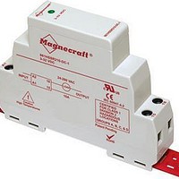
861SSRA208-DC-2 Magnecraft / Schneider Electric, 861SSRA208-DC-2 Datasheet
861SSRA208-DC-2
Specifications of 861SSRA208-DC-2


Related parts for 861SSRA208-DC-2


861SSRA208-DC-2 Summary of contents
Page 1
Solid State Relays Catalog 2010 ...
Page 2
Contents 2 Magnecraft Solid State Relays ® Series Overview � � � � � � � � � � � � � � � � � � � � � � � � � � � � � � � ...
Page 3
Series Overview Defining Series Feature Slim 861 17�5 mm profile 861 Relay Class 1, Division 2 certified 861H for use in hazardous 861H Relay locations Integrated heat sink and SSRDIN high current switching capacity SSRDIN Relay High current switching 6000 ...
Page 4
Description 861 Relay Switching Switching Input Voltage Type Device Range DC switching MOSFET (1) 3�5–32 Vdc 3–32 Vdc Random SCR (2) 90–280 Vac 3–32 Vdc Zero cross SCR 90–280 Vac (1) MOSFET = metal oxide semiconductor field-effect transistor (2) SCR ...
Page 5
Specifications Specifications (UL 508) Part Number Input Characteristics Input Voltage Range Must Release Voltage Nominal Input Impedance Typical Input Current at 5 Vdc Reverse Polarity Protection Output Characteristics Switching Device Switching Type Contact Configuration Output Voltage Range Maximum Rate of ...
Page 6
Dimensions, Wiring Diagram, De-Rating Curves Dimensions: Inches (Millimeters) 0.2 (6) 0.7 (17.6) 0.56 0.2 (14.2) (5.0) INPUT 3.5 (90) 1.8 (45.3) 2.6 (66.8) OUTPUT 0.7 0.3 (16.0) (6.9) 1.4 (34.6) Wiring Diagram INPUT POWER SUPPLY MOSFET ONLY + - A2 ...
Page 7
Description Class 1, Division 2 certification for use in hazardous locations. (Temperature code: T5) 861H Relay Switching Switching Input Voltage Type Device Range DC switching MOSFET 3.5–32 Vdc 3–32 Vdc Zero cross SCR (2) 90–280 Vac Part Number Explanation Series: ...
Page 8
Specifications Specifications (UL 508) Part Number Input Characteristics Input Voltage Range Must Release Voltage Nominal Input Impedance Typical Input Current at 5 Vdc Reverse Polarity Protection Output Characteristics Switching Device Switching Type Contact Configuration Output Voltage Range Maximum Rate of ...
Page 9
Dimensions, Wiring Diagram, De-Rating Curves Dimensions: Inches (Millimeters) 0.2 (6) 0.7 (17.6) 0.56 0.2 (14.2) (5.0) INPUT 3.5 (90) 1.8 (45.3) 2.6 (66.8) OUTPUT 0.7 0.3 (16.0) (6.9) 1.4 (34.6) 2.6 MAX. Wiring Diagram INPUT POWER SUPPLY MOSFET ONLY + ...
Page 10
Description SSRDIN Relay Switching Input Voltage Switching Type Device Range DC switching MOSFET 4–32 Vdc 4–32 Vdc 3–32 Vdc 4–32 Vdc Zero cross SCR 90–280 Vac 90–140 Vac 90–280 Vac (1) No agency approvals on MOSFET versions Part Number Explanation ...
Page 11
Specifications Specifications (UL 508) Part Number SSR2••DIN-DC•• Input Characteristics Input Voltage Range 4–32 Vdc Maximum Turn-On Voltage 4 Vdc Minimum Turn-Off Voltage 1 Vdc Typical Input Current 8–12 mA Output Characteristics Output Type SCR Switching Type Zero voltage Output Voltage ...
Page 12
Dimensions, Wiring Diagram, De-Rating Curves Dimensions: Inches (Millimeters) MOUNTING HOLE 0.17 (4.3) DIA. INPUT 2.61 (66.2) 3.53 (89. 3.15 (80.0) OUTPUT 0.44 (11.2) 0.88 3.15 (22.4) (80.0) 3.8 (97.7) Wiring Diagram INPUT POWER SUPPLY MOSFET ONLY + - ...
Page 13
Description 6000 Series Relays Switching Input Voltage Switching Type Device Range DC switching MOSFET 3.5–32 Vdc 3–32 Vdc SCR Zero cross 90–280 Vac Triac 3–32 Vdc * Blade terminals. Part Number Explanation Series 6000 Output Voltage ...
Page 14
Specifications pecifications (UL 508) S Part Number Input Characteristics Control Voltage Range Maximum Turn-On Voltage Minimum Turn-Off Voltage Nominal Input Impedance Typical Input Current Output Characteristics Switching Device Switching Type Contact Configuration Output Current Range Output Voltage Range (47–63 Hz) ...
Page 15
Specifications (continued) Specifications (UL 508) Part Number Input Characteristics Control Voltage Range Maximum Turn-On Voltage Minimum Turn-Off Voltage Nominal Input Impedance Typical Input Current Output Characteristics Switching Device Switching Type Contact Configuration Output Current Range Output Voltage Range Transient Over-voltage ...
Page 16
Dimensions, Wiring Diagram, De-Rating Curves Dimensions: Inches (Millimeters) 1.4 (35.9) Side View 2.28 (57.91) 1.7 (43.42) Side View (25 & MOSFET versions only) Wiring Diagram INPUT POWER SUPPLY MOSFET ONLY + - 4 (-) SSR 3 (+) De-Rating ...
Page 17
Description SSR-HS-1 SSR-TP-1 Description Function Heat sink Maximizes heat dissipation Simplifies installation with a simple Thermal pad peel-and-stick solution, which does not require messy thermal grease Magnecraft Solid State Relays ® Accessories for 6000 Series Heat Sink, SSR-HS-1 Thermal Pad, ...
Page 18
Dimensions, De-Rating Curves Dimensions: Inches (Millimeters) SSR-HS-1 0.19 (4.95) 1.75 (44.45) 0.13 (3.18) TOP VIEW 4.73 (120.14) 3.86 (97.92) 1.99 0.24 (50.63) (6.04) FRONT VIEW 0.34 (8.69) De-Rating Curves (when used with thermal pad and heat sink) Thermal Resistance vs ...
Page 19
Description 70S2 (V) Relay 70S2 (F) Relay 70S2 (S) Relay 70S2 (M) Relay 70S2 (N) Relay Switching Switching Input Voltage Type Device Range 3–15 Vdc DC switching MOSFET 9–30 Vdc 3–30 Vdc Zero cross Triac 3–32 Vdc 6–30 Vdc Part ...
Page 20
Specifications Specifications (UL 508) Part Number Input Characteristics Control Voltage Range Must Release Voltage Typical Input Current Maximum Reverse Control Voltage Output Characteristics Switching Device Switching Type Contact Configuration Output Voltage Range Peak Blocking Voltage Maximum Rate of Rise Off ...
Page 21
Specifications (continued) Specifications (UL 508) Part Number Input Characteristics Control Voltage Range Must Release Voltage Typical Input Current Maximum Reverse Control Voltage Output Characteristics Switching Device Switching Type Contact Configuration Output Voltage Range Peak Blocking Voltage Maximum Rate of Rise ...
Page 22
Dimensions Dimensions: inches (millimeters) 0.6 (15.2) 0.2 (5.1) 0.5 (11.4) OUTPUT 1.2 (31.2) INPUT 0.3 (7.6) 0.4 0.3 (10.2) (7.6) 1.0 (26.2) - 0.8 INPUT (20.7) + 0.5 (12.7) 0.25 0.2 (6.5) (4.4) 1.9 (47.5) OUTPUT 0.9 1.2 (22.9) 2.2 ...
Page 23
Dimensions , (continued) 0.9 MAX Wiring Diagram, INPUT (22.9) De-Rating Curves Dimensions: inches (millimeters) 0.16 (4.1) 1.7 (43.2) 1.02 0.2 (26.0) (5.1) INPUT OUTPUT – + – + 0.3 (7.6) 0.4 (10.2) 0.9 (22.9) 1.1 (27.9) Wiring Diagram INPUT ...
Page 24
Application Data 24 Magnecraft Solid State Relays ® Definition A solid state relay (SSR) can perform many tasks that an electromechanical relay (EMR) can perform� The SSR differs in that it has no moving mechanical parts� essentially an ...
Page 25
Application Data (continued) Electronic Appliances Domestic appliances, cooking appliances, heating elements, audio equipment Food & Beverage Commercial/industrial cooking equipment, ltration systems, bottleing, chillers, convection ovens High Reliability Medical equipment, lifts & escalators, low switching noise, low electromagnetic interference, automatic door ...
Page 26
Application Data (continued) 26 Magnecraft Solid State Relays ® Thermal Considerations One of the major considerations when using a SSR is properly managing the heat that is generated when switching currents are higher than 5 A� In this scenario mount ...
Page 27
Application Data (continued) Magnecraft Solid State Relays ® Heat Sinking Thermal management is a fundamental consideration in the design and use of solid state relays because of the dissipation (typically 1 watt per amp)� It is, therefore, vital that an ...
Page 28
Application Data (continued) 28 Magnecraft Solid State Relays ® Load Considerations The major cause of application problems with SSRs is improper heat sinking� Following that are issues which result from operating conditions which specific loads impose upon an SSR� Carefully ...
Page 29
Application Data (continued) Magnecraft Solid State Relays ® Transformers In controlling transformers, consider the characteristics of the secondary load because they reflect the effective load on the SSR� Voltage transients from secondary loads circuits, similarly, are frequently transformers and can ...
Page 30
Selection Guide 30 Magnecraft Solid State Relays ® The Magnecraft Range of Solid State Relays Depending on the application, the Magnecraft line of solid state relays offers a number of advantages over electromechanical relays, including longer life cycles, less energy ...
Page 31
Website Guide 3D Models Time Delay Relay Demo Magnecraft Solid State Relays ® The Magnecraft website (www.magnecraft.com) to easily find the proper relay to fit design requirements and to help simplify and shorten workflow� Easily find the proper relay to ...
Page 32
Schneider Electric USA, Inc. 1300 S� Wolf Rd� Des Plaines, IL 60018 Tel: 847-441-2540 The information and dimensions in this catalog are provided for the convenience of our customers� While this information is believed to be accurate, Schneider Electric reserves ...