FEP16DT-E3/45 Vishay, FEP16DT-E3/45 Datasheet

DIODE 16A 200V 35NS DUAL TO220-3

FEP16DT-E3/45

Manufacturer Part Number
FEP16DT-E3/45
Description
DIODE 16A 200V 35NS DUAL TO220-3
Manufacturer
Vishay
Datasheets

Specifications of FEP16DT-E3/45

Diode Configuration
1 Pair Common Cathode
Diode Type
Standard
Voltage - Forward (vf) (max) @ If
950mV @ 8A
Current - Reverse Leakage @ Vr
10µA @ 200V
Current - Average Rectified (io) (per Diode)
8A
Voltage - Dc Reverse (vr) (max)
200V
Reverse Recovery Time (trr)
35ns
Speed
Fast Recovery =< 500ns, > 200mA (Io)
Mounting Type
Through Hole
Package / Case
TO-220-3 (Straight Leads)
Product
Ultra Fast Recovery Rectifier
Configuration
Dual Common Cathode
Reverse Voltage
200 V
Forward Voltage Drop
0.95 V @ 8 A
Recovery Time
35 ns
Forward Continuous Current
16 A
Max Surge Current
200 A
Reverse Current Ir
10 uA
Mounting Style
Through Hole
Maximum Operating Temperature
+ 150 C
Minimum Operating Temperature
- 55 C
Repetitive Reverse Voltage Vrrm Max
200V
Forward Current If(av)
16A
Forward Voltage Vf Max
950mV
Lead Free Status / RoHS Status
Lead free / RoHS Compliant
Lead Free Status / RoHS Status
Lead free / RoHS Compliant, Lead free / RoHS Compliant

Available stocks

Company
Part Number
Manufacturer
Quantity
Price
Part Number:
FEP16DT-E3/45
Manufacturer:
Vishay Semiconductors
Quantity:
1 000
Part Number:
FEP16DT-E3/45
Manufacturer:
VISHAY/威世
Quantity:
20 000
Company:
Part Number:
FEP16DT-E3/45
Quantity:
70 000
Document Number: 88596
Revision: 07-Nov-07
PRIMARY CHARACTERISTICS
MAXIMUM RATINGS (T
PARAMETER
Maximum repetitive peak reverse voltage
Maximum RMS voltage
Maximum DC blocking voltage
Maximum average forward
rectified current at T
Peak forward surge current 8.3 ms
single half sine-wave superimposed
on rated load per diode
Operating storage and temperature range
Isolation voltage (ITO-220AB only)
from terminal to heatsink t = 1 min
FEP16xT
PIN 1
PIN 3
TO-220AB
T
V
I
J
I
F(AV)
FSM
RRM
V
t
max.
rr
F
Dual Common-Cathode Ultrafast Plastic Rectifier
PIN 2
CASE
C
= 100 °C
FEPB16xT
PIN 2
PIN 1
1
K
TO-263AB
2
3
C
1
= 25 °C unless otherwise noted)
0.95 V, 1.30 V, 1.50 V
HEATSINK
K
2
FEPF16xT
PIN 1
PIN 3
50 V to 600 V
ITO-220AB
200 A, 125 A
35 ns, 50 ns
8.0 A x 2
SYMBOL
150 °C
T
J
V
V
I
I
V
F(AV)
, T
V
FSM
RRM
RMS
DC
AC
STG
PIN 2
1
16AT
FEP
50
35
50
2
3
16BT
FEP
100
100
70
FEP(F,B)16AT thru FEP(F,B)16JT
200
FEATURES
TYPICAL APPLICATIONS
For use in high frequency rectifier of switching mode
power supplies, inverters, freewheeling diodes,
dc-to-dc converters, and other power switching
application.
MECHANICAL DATA
Case: TO-220AB, ITO-220AB, TO-263AB
Epoxy meets UL 94V-0 flammability rating
Terminals: Matte tin plated leads, solderable per
J-STD-002B and JESD22-B102D
E3 suffix for commercial grade, meets JESD 201 class
1A whisker test, HE3 suffix for high reliability grade
(AEC Q101 qualified), meets JESD 201 class 2
whisker test
Polarity: As marked
Mounting Torque: 10 in-lbs maximum
• Glass passivated chip junction
• Ultrafast recovery time
• Low switching losses, high efficiency
• High forward surge capability
• AEC Q101 qualified
• Meets MSL level 1, per J-STD-020C, LF maximum
• Solder dip 260 °C, 40 s (for TO-220AB and
• Component in accordance to RoHS 2002/95/EC
16CT
peak of 245 °C (for TO-263AB package)
ITO-220AB package)
and WEEE 2002/96/EC
FEP
150
105
150
Vishay General Semiconductor
16DT
FEP
200
140
200
- 55 to +150
1500
16
16FT
FEP
300
210
300
16GT
FEP
400
280
400
125
16HT
FEP
500
350
500
www.vishay.com
16JT
FEP
600
420
600
UNIT
°C
V
V
V
A
A
V
1

Related parts for FEP16DT-E3/45

FEP16DT-E3/45 Summary of contents

Page 1

... RRM 105 RMS V 50 100 150 DC I F(AV) I 200 FSM STG V AC Vishay General Semiconductor FEP FEP FEP FEP FEP 16DT 16FT 16GT 16HT 16JT 200 300 400 500 600 140 210 280 350 420 200 300 400 500 ...

Page 2

... FEP(F,B)16AT thru FEP(F,B)16JT Vishay General Semiconductor ELECTRICAL CHARACTERISTICS (T PARAMETER TEST CONDITIONS Maximum instantaneous 8.0 A (1) forward voltage per diode Maximum DC reverse current per diode at rated DC blocking voltage Maximum reverse recovery time per diode Typical junction capacitance 4 MHz per diode Note: (1) Pulse test: 300 µ ...

Page 3

... Figure 4. Typical Reverse Characteristics Per Diode 1000 100 10 0.1 100 Figure 5. Typical Junction Capacitance Per Diode ° 400 V 300 - 400 V 500 - 600 V 1.6 1.8 2.0 Vishay General Semiconductor T = 125 ° 400 V J 500 - 600 100 ° ° Percent of Rated Peak Reverse Voltage (%) T = 125 ° ...

Page 4

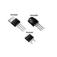
... FEP(F,B)16AT thru FEP(F,B)16JT Vishay General Semiconductor PACKAGE OUTLINE DIMENSIONS in inches (millimeters) TO-220AB 0.415 (10.54) MAX. 0.370 (9.40) 0.154 (3.91) 0.360 (9.14) 0.148 (3.74) 0.113 (2.87) 0.103 (2.62) 0.145 (3.68) 0.135 (3.43) 0.635 (16.13) 0.625 (15.87) PIN 0.350 (8.89 0.330 (8.38) 0.160 (4.06) 1 ...

Page 5

... Information contained herein is intended to provide a product description only. No license, express or implied, by estoppel or otherwise, to any intellectual property rights is granted by this document. Except as provided in Vishay's terms and conditions of sale for such products, Vishay assumes no liability whatsoever, and disclaims any express or implied warranty, relating to sale and/or use of Vishay products including liability or warranties relating to fitness for a particular purpose, merchantability, or infringement of any patent, copyright, or other intellectual property right ...

Related keywords